Battery cooling system

a battery cooling and battery technology, applied in the direction of battery/fuel cell control arrangement, electric devices, battery/cell propulsion, etc., can solve the problem of insufficient suppression of battery temperature rise, achieve effective cooling of battery, effectively suppress battery temperature rise, and overcome drawbacks

Inactive Publication Date: 2008-04-08
NISSAN MOTOR CO LTD
View PDF12 Cites 64 Cited by
  • Summary
  • Abstract
  • Description
  • Claims
  • Application Information

AI Technical Summary

Benefits of technology

[0004]It is, therefore, an object of the present invention to provide an improved battery cooling system which can effectively overcome drawbacks encountered in conventional battery cooling systems of the similar nature.
[0005]Another object of the present invention is to provide an improved battery cooling system which can effectively cool a battery by using travel air flow generated with traveling of a vehicle.
[0006]A further object of the present invention is to provide an improved battery cooling system which can effectively suppress a temperature rise of a battery during stopping of traveling of the vehicle.

Problems solved by technology

However, with the above proposition, there arises problems that travel air flow cannot be effectively struck against the battery under restriction conditions such as the size of the battery, the mounting position of the battery, or the like, thereby making it impossible to sufficiently suppress a temperature rise of the battery.

Method used


Image

  • Battery cooling system
  • Battery cooling system
  • Battery cooling system

Examples


Embodiment Construction

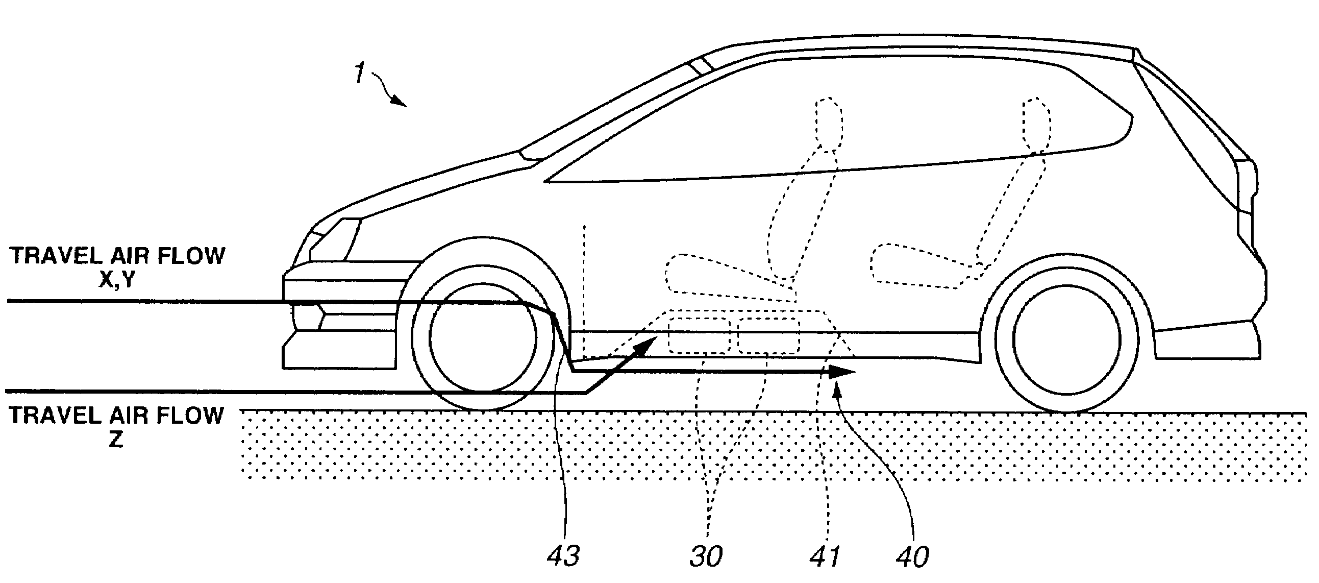
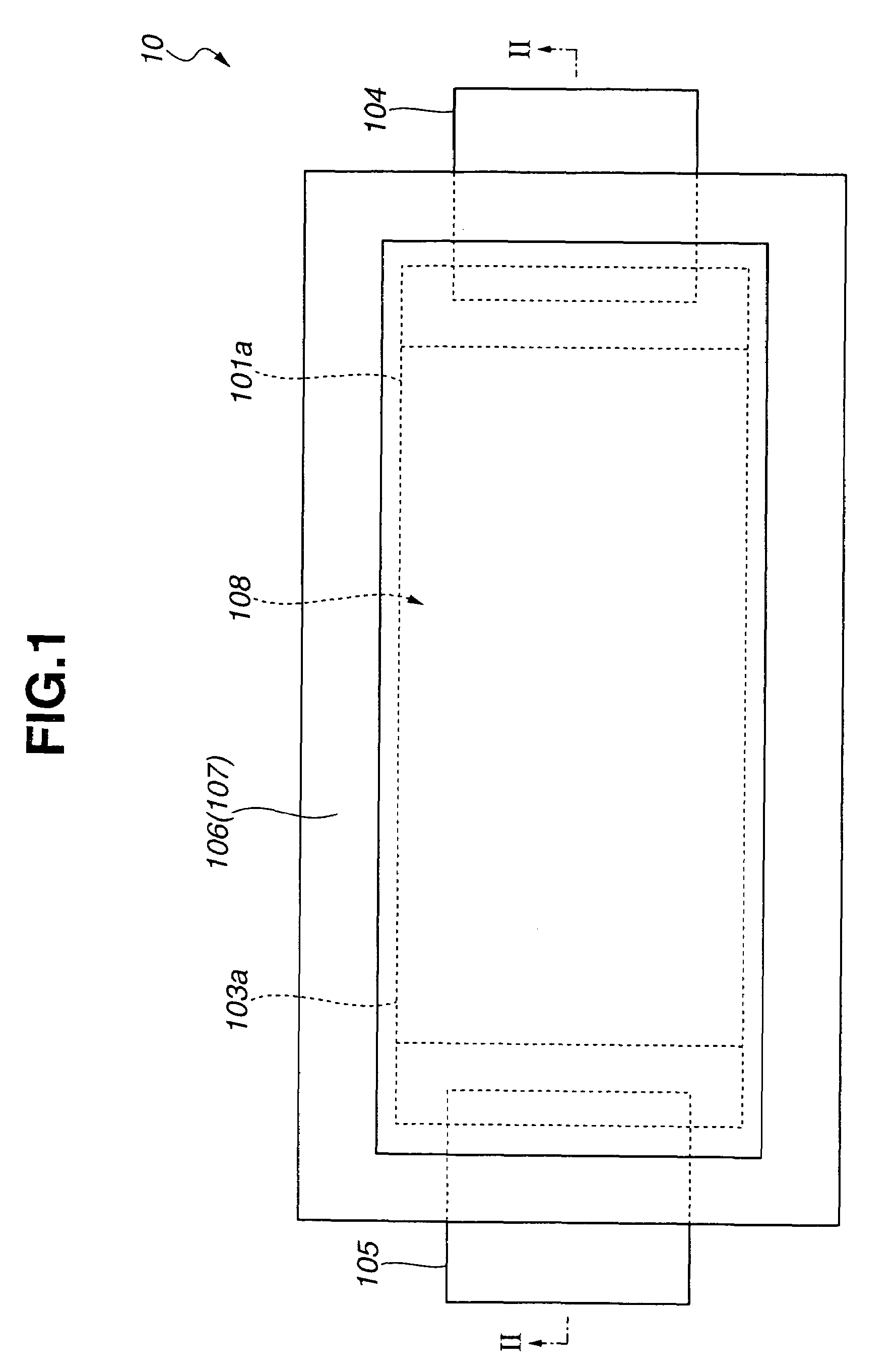
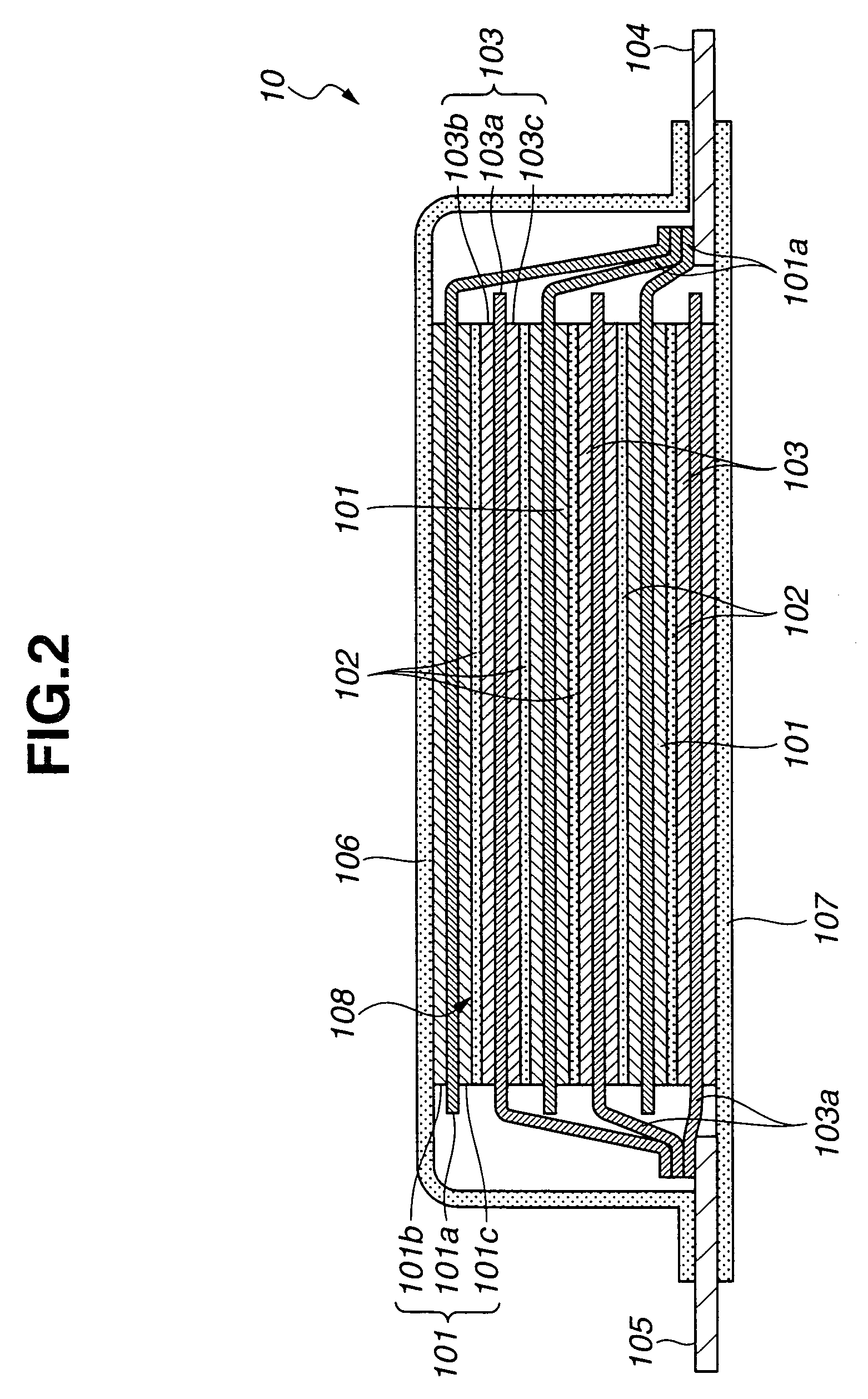
[0027]Referring now to FIGS. 1 to 8E of the drawings, an embodiment of battery cooling system 40 according to the present invention is illustrated. The battery cooling system comprises a battery 30 which is constituted of a plurality of thin cell (or laminate cell) 10 each of which serves as a unit cell. Accordingly, these thin cells 10 are laminated to constitute the battery having a desired voltage and capacity as shown in FIGS. 1 and 2. FIG. 1 is a plan view of the whole body of the thin cell forming part of the battery used in the embodiment of the battery cooling system; and FIG. 2 is a sectional view taken in the direction of arrows substantially along the line II-II of FIG. 1.

[0028]As illustrated in FIGS. 1 and 2, each thin cell 10 of battery 30 of the present invention is a lithium ion secondary (rechargeable) cell which is able to be laminated or piled up on another similar lithium ion secondary cell. Each thin cell 10 includes three anode plates 101 and three cathode plate...


PUM


Abstract

A battery cooling system includes a depression-shaped battery accommodating section formed at a bottom surface of a floor panel of a vehicle and dented to side of a passenger compartment so as to accommodate therein a battery. An introduction device is disposed in front of the battery in a vehicle traveling direction, to introduce travel air flow into the battery accommodating section. Here, the battery is accommodated within the battery accommodating section in a condition where a bottom surface of the battery is located at a level above or at a substantially same level as a level of a bottom surface of the vehicle which bottom surface is around the accommodating section. Additionally, the battery includes a plurality of thin cells which are electrically connected with each other, and disposed in a posture that a major surface of each thin cell extends substantially parallelly with the vehicle traveling direction.

Description

BACKGROUND OF THE INVENTION[0001]This invention relates to improvements in a battery cooling system in which a battery is cooled by using travel air flow generated with traveling of a vehicle.[0002]In order to cool a battery mounted as a driving power source on, for example, an electric vehicle (EV), a hybrid electric vehicle (HEV), a fuel cell powered vehicle (FCV) and the like, it has been proposed to use travel air flow as a cooling medium, generated with traveling of the vehicle.BRIEF SUMMARY OF THE INVENTION[0003]However, with the above proposition, there arises problems that travel air flow cannot be effectively struck against the battery under restriction conditions such as the size of the battery, the mounting position of the battery, or the like, thereby making it impossible to sufficiently suppress a temperature rise of the battery.[0004]It is, therefore, an object of the present invention to provide an improved battery cooling system which can effectively overcome drawbac...

Claims


Application Information

Patent Timeline
Patent Type & Authority Patents(United States)
IPC IPC(8): B60R16/04
CPCB60R16/04B60L3/0046B60L50/64B60L50/66B60L58/18B60L58/26Y02T10/70
Inventor ABE, TAKAAKISUZUKI, MASAAKIHORIE, HIDEAKI
Owner NISSAN MOTOR CO LTD
Why Eureka
Try Eureka