Blade for a rotor of a wind energy turbine

a technology of wind energy turbine and blade, which is applied in the direction of machines/engines, mechanical equipment, transportation and packaging, etc., can solve the problems of root and tip vorticities, disadvantages not only in aerodynamic performance but also in generation

Active Publication Date: 2008-04-08
GENERAL ELECTRIC CO
View PDF21 Cites 82 Cited by
  • Summary
  • Abstract
  • Description
  • Claims
  • Application Information

AI Technical Summary

Problems solved by technology

The aerodynamic performance of a rotor blade is limited by undesired generation of vorticities at the root and the tip of the blade and by the location of the transition lines at the upper and lower faces of the blade along which lines the air stream converts from a laminar flow to a turbulent flow which no longer can be used for aerodynamic lift-off effects acting on the blade.
In particular root and tip vorticities are disadvantageous not only with respect to the aerodynamic performances but also with respect to the generation of undesired noise and turbulence shadings affecting adjacent wind energy turbines in a wind park.

Method used


Image

  • Blade for a rotor of a wind energy turbine
  • Blade for a rotor of a wind energy turbine
  • Blade for a rotor of a wind energy turbine

Examples


Embodiment Construction

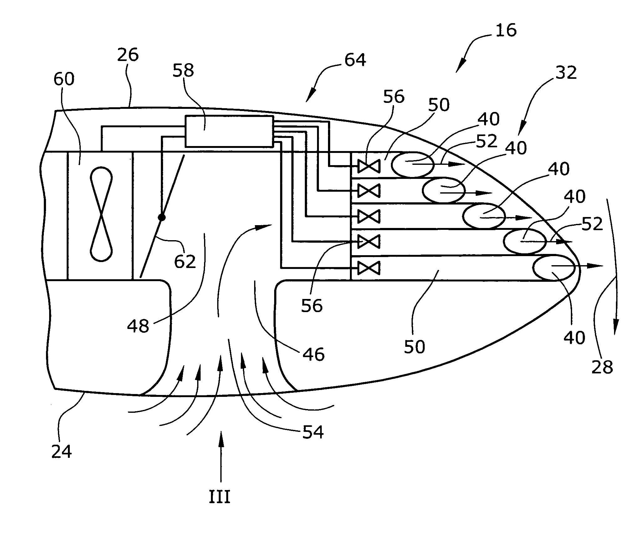
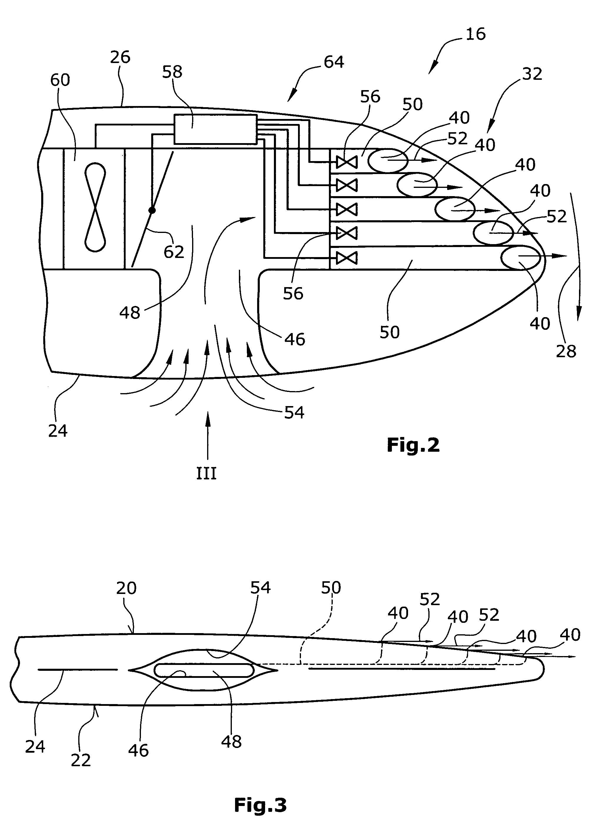
[0010]In one embodiment of the invention, at least one outlet opening for discharging pressurized air is arranged in at least one of opposite upper and lower faces and / or the trailing edge of the blade along which the upper and lower faces of the blade are connected, such as along the leading edge of the blade. The pressurized air is generated by means for generating pressurized air. This means can be operable as an active or passive means generating the pressurized air with the aid of a fan or the like or by receiving air of an air stream which the blade is subjected to during operation and releasing this air as pressurized air via the at least one outlet opening. In one embodiment, the means for generating pressurized air can be designed both as passive and active means.

[0011]The at least one outlet opening is, in one embodiment, arranged e.g. at the tip of a rotor blade in that face thereof which is subjected to suction of the air flowing along the face. Around the tip there is a...


PUM


Abstract

A blade for a rotor of a wind energy turbine includes opposite upper and lower faces, opposite leading and trailing edges connecting the upper and lower and at least one air outlet opening arranged on at least one of the upper face, the lower face and the trailing edge for discharging pressurized air into the air around at least one of the upper and lower faces and the leading and trailing edges.

Description

BACKGROUND OF THE INVENTION[0001]This invention relates to a blade for a rotor of a wind energy turbine and, in particular, to a system for influencing the aerodynamic boundary layer around the blade when subjected to an air stream.[0002]To enhance the overall performance of wind energy turbines one approach is to improve the aerodynamic characteristics of the rotor blades. The aerodynamic performance of a rotor blade is limited by undesired generation of vorticities at the root and the tip of the blade and by the location of the transition lines at the upper and lower faces of the blade along which lines the air stream converts from a laminar flow to a turbulent flow which no longer can be used for aerodynamic lift-off effects acting on the blade. In particular root and tip vorticities are disadvantageous not only with respect to the aerodynamic performances but also with respect to the generation of undesired noise and turbulence shadings affecting adjacent wind energy turbines in...

Claims


Application Information

Patent Timeline
Patent Type & Authority Patents(United States)
IPC IPC(8): B64C11/24
CPCF03D1/0633F03D11/022F05B2240/30Y02E10/721Y02E10/722Y10S415/905F03D15/05Y02E10/72
Inventor BONNET, LAURENT
Owner GENERAL ELECTRIC CO
Why Eureka
Try Eureka