
System and method for improved multiple-dimension image displays

a multi-dimension image and display system technology, applied in the field of interactive image processing apparatus, can solve the problems of large number of two-dimensional data slices, affecting the visual system, and affecting the quality of volume-rendered images,

Active Publication Date: 2008-04-08
KONINKLIJKE PHILIPS ELECTRONICS NV
View PDF3 Cites 83 Cited by
  • Summary
  • Abstract
  • Description
  • Claims
  • Application Information

AI Technical Summary

Benefits of technology

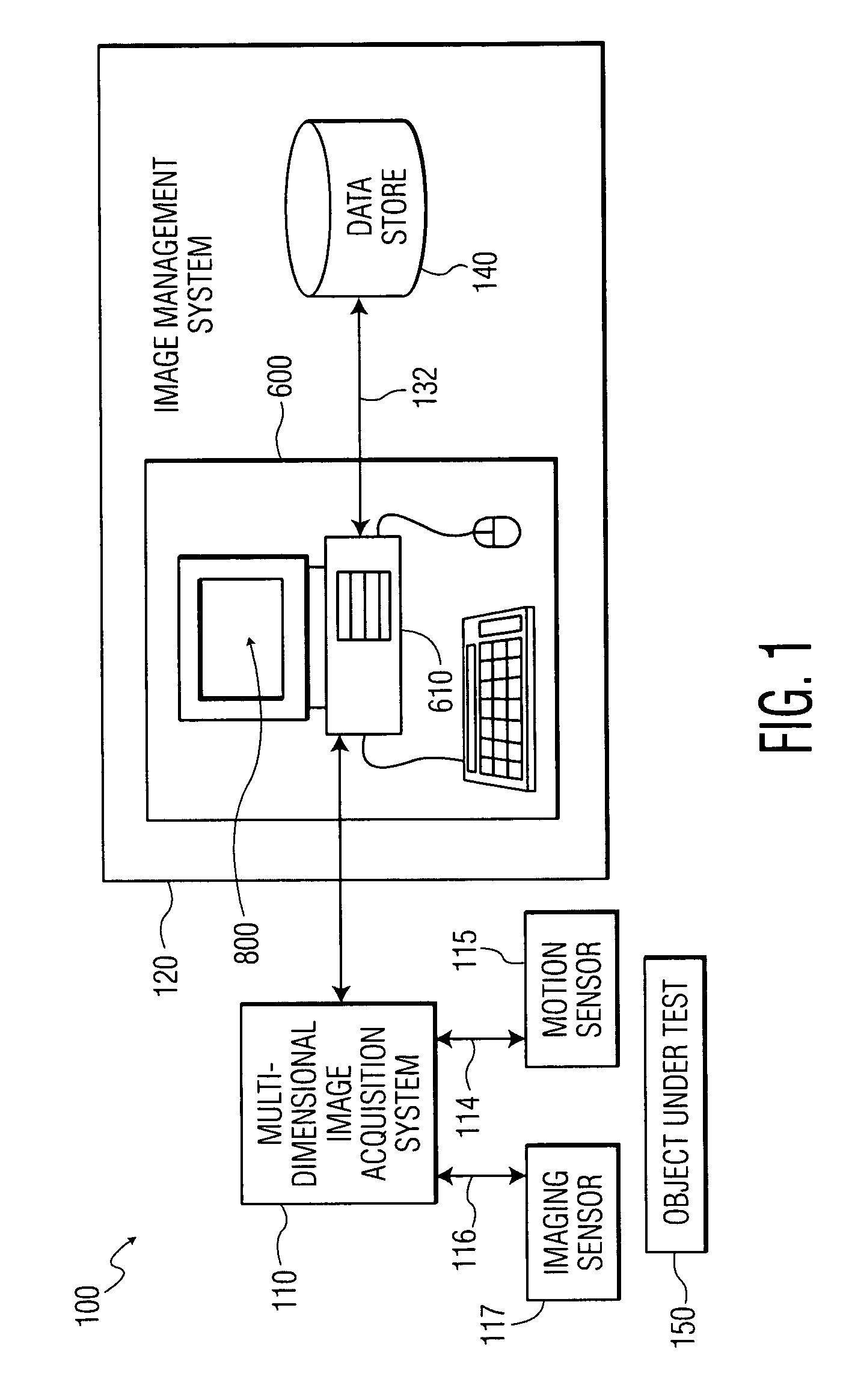
[0009]An improved multiple-dimensional imaging system comprises a memory-storage unit configured to store a multiple-dimensional data set, an image processor communicatively coupled to the memory-storage unit, the image processor configured to convert the multiple-dimensional data set to a two-dimensional representation in a plane orthogonal to an operator-identified view axis, and ...

Problems solved by technology

The integration of a large number of two-dimensional data slices places great strain on the human visual system, even for relatively simple volumetric images.
As the organ or tissue under investigation becomes more complex, the ability to properly integrate large amounts of two-dimensional data to produce meaningful and understandable three-dimensional mental images may become overwhelming.
Prior art methods exist for displaying representations of slices of processed digital data; however, the operator oftentimes must mentally reconstruct the two-dimensional slices into a volumetric image using his existing knowledge of anatomy.
While volume rendered data contains all the detail available from the two-dimensional data sets from which they are constructed, clinicians often report that the projected quality of volume-rendered images is not as clear as a two-dimensional image.

Method used


Image

  • System and method for improved multiple-dimension image displays
  • System and method for improved multiple-dimension image displays
  • System and method for improved multiple-dimension image displays

Examples


Embodiment Construction

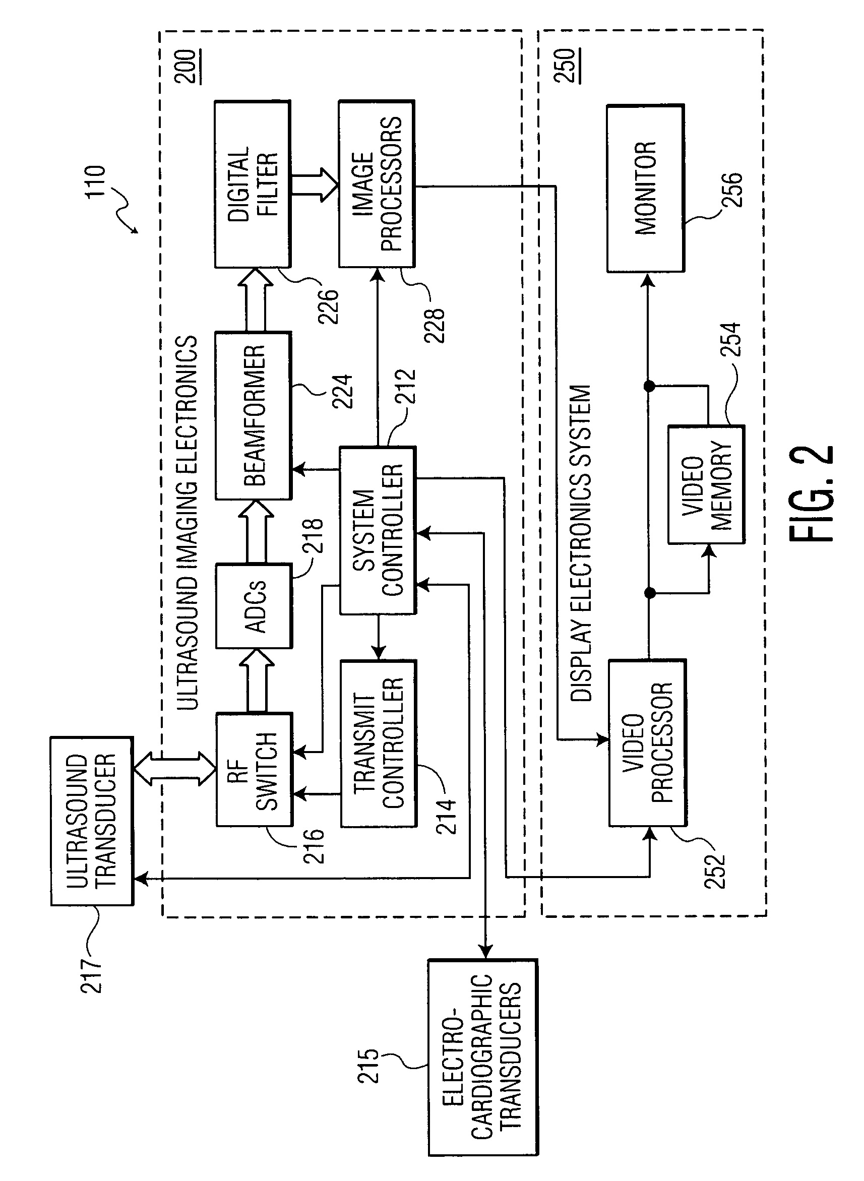
[0022]Ultrasound-imaging systems can create two-dimensional brightness or B-mode images of tissue in which the brightness of a pixel is based on the intensity of the received ultrasound echoes. In another common imaging modality, typically known as color-flow imaging, the flow of blood or movement of tissue is observed. Color-flow imaging takes advantage of the Doppler effect to color-encode image displays. In color-flow imaging, the frequency shift of backscattered-ultrasound waves is used to measure the velocity of the backscatterers from tissues or blood. The frequency of sound waves reflecting from the inside of blood vessels, heart cavities, etc. is shifted in proportion to the velocity of the blood cells. The frequency of ultrasound waves reflected from cells moving towards the transducer is positively shifted. Conversely, the frequency of ultrasound reflections from cells moving away from the transducer is negatively shifted. The Doppler shift may be displayed using different...


PUM


Abstract

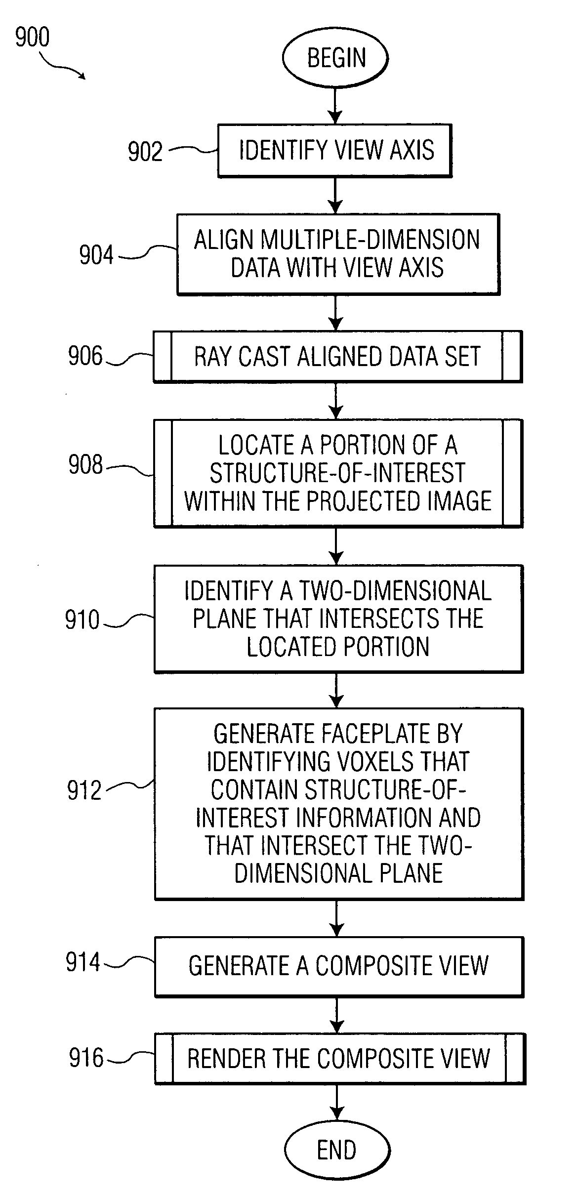
An improved imaging system includes a memory-storage unit, a multiple-dimensional image processor configured to convert information within a multiple-dimensional data set to a two-dimensional representation in a plane orthogonal to an operator-identified view axis, and an image-rendering device configured to display the two-dimensional representation of a volume-of-interest contained within the three-dimensional data set, wherein the two-dimensional representation is responsive to pixel values associated with a faceplate orthogonal to the view axis. A method for viewing information includes identifying a view axis that intersects a multiple-dimensional data set, modifying the multiple-dimensional data set to align the multiple-dimension data set responsive to the view axis, locating a portion of a structure-of-interest along a vector parallel to view axis, associating a set of pixels with a faceplate, and generating a composite view in accordance with the faceplate.

Description

CROSS REFERENCE TO RELATED APPLICATION[0001]This application claims the benefit of application Ser. No. 60 / 437,512, filed on Dec. 31, 2002.TECHNICAL FIELD[0002]The present system and method relates generally to an image-processing apparatus for generating a multiple-dimension image of one or more objects from volume data, and more particularly to an interactive image-processing apparatus for improving contrast of objects within the volume data.DESCRIPTION OF THE RELATED ART[0003]While the examination of data which fills a three-dimensional space occurs in all branches of art, science, and engineering, some important and familiar examples involve medical imaging where, for example, computer-aided tomography (CAT or CT), magnetic-resonance imaging (MRI), and other scanning modalities are used to obtain a plurality of cross-sectional images of the human anatomy. Radiologists, physicians, technicians, and patients observe two-dimensional data “slices” to discern what the two-dimensional...

Claims


Application Information

Patent Timeline
IPC IPC(8): G06K9/00G06K9/40G06T15/08
CPCG06T15/08
Inventor ZIEL, JONATHAN MARKTHIELE, KARL
Owner KONINKLIJKE PHILIPS ELECTRONICS NV
Learn More