Slider for slide fastener and slider having a spring body mounted thereon

a technology of slide fastener and spring body, which is applied in the direction of snap fasteners, separation processes, filtration separation, etc., can solve the problems of lack of flexibility, spring pieces that do not return to the original state, narrow oscillation range of spring pieces, etc., to improve smooth deformation of the spring pieces. , the effect of improving the ruggedness of the spring body

Active Publication Date: 2008-04-15
YKK CORP
View PDF15 Cites 8 Cited by
  • Summary
  • Abstract
  • Description
  • Claims
  • Application Information

AI Technical Summary

Benefits of technology

[0045]Operating the pull, in connection with the operation of the pull, the spring piece of the spring body is oscillated around the hook portion of the spring body that is freely fit and hooked on the projection piece portion that is protruded on the upper portion of the first post portion while elastically deforming the pawl portion of the spring body in a direction to be engaged with or be released from the coupling

Problems solved by technology

In the meantime, upon forming such a kind of spring piece, when a base portion of the spring piece is cut out obliquely upward directly from a longitudinal middle portion of the elastic metal platy material and a horse-shoe shaped cut-out hole is formed, an oscillation range of the spring piece becomes narrow and it lacks flexibility.
Therefore, when the entire spring body is oscillated and this spring piece is fit in the cut-out hole of this spring piece and is hooked in the cut-out hole, this involves a problem such that the spring piece does not return to the original state and the automatic stop function of the slider is lost.
Therefore, for example, when the spring piece is molded from the metal material having a strong spring property, if the very small part such as the spring piece requires a cut-out processing and a bending processing much, this involves a problem such that the spring piece suffers some cracks during processing or abrasion of a blanking punch blade is hastened.
In other words, if the excess force is applied to the front end portion of the spring piece, the spring piece is cut and damaged or it suffers some cracks.
Accordingly, it is not possible to improve a processing precision of the front end portion of the spring piece to expect the stability of the figuration and further, there is a limitation in manufacturing many products with a high precision.
In addition, according to such a cut-out processing, it is impossible to mold a spring body without producing broken ends, broken waste or the like by cutting out, and many scraps such as the broken ends or the like due to cutting out upon molding the spring body occur.
Therefore, such a structure uses materials wastefully and this has limitati

Method used


Image

  • Slider for slide fastener and slider having a spring body mounted thereon
  • Slider for slide fastener and slider having a spring body mounted thereon
  • Slider for slide fastener and slider having a spring body mounted thereon

Examples


Embodiment Construction

[0058]Preferred embodiments of the invention will be specifically described below with reference to the drawings.

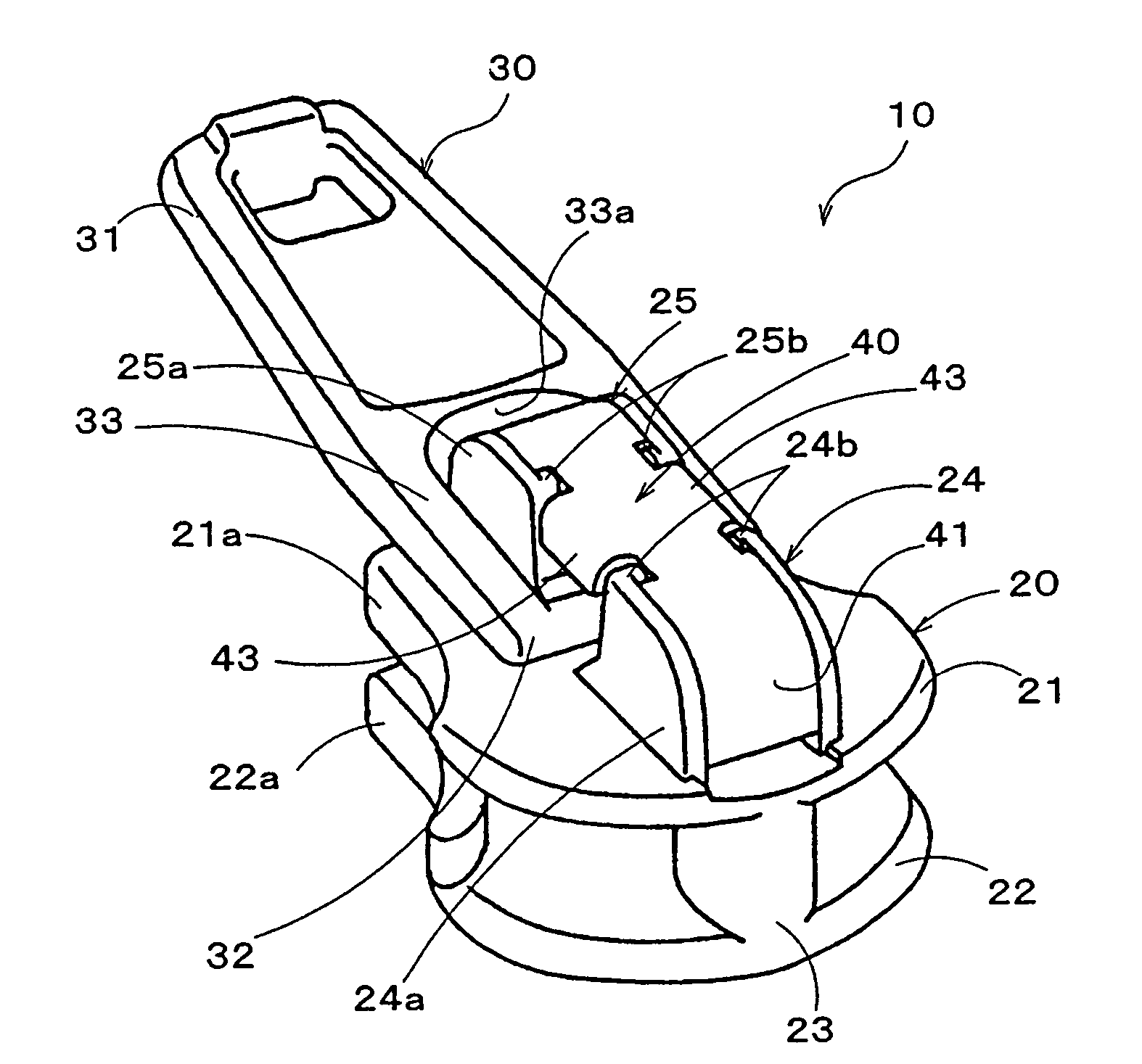
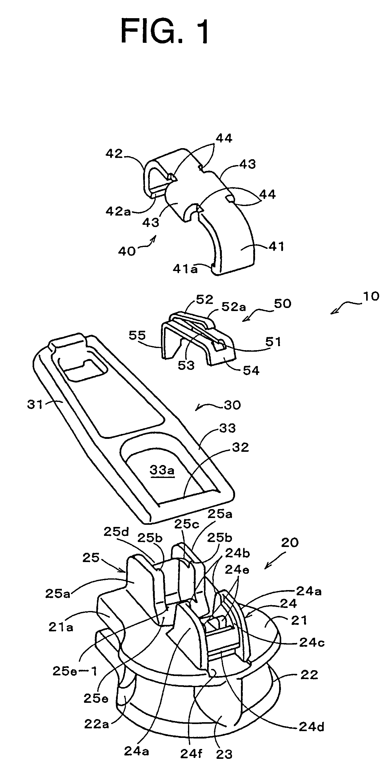
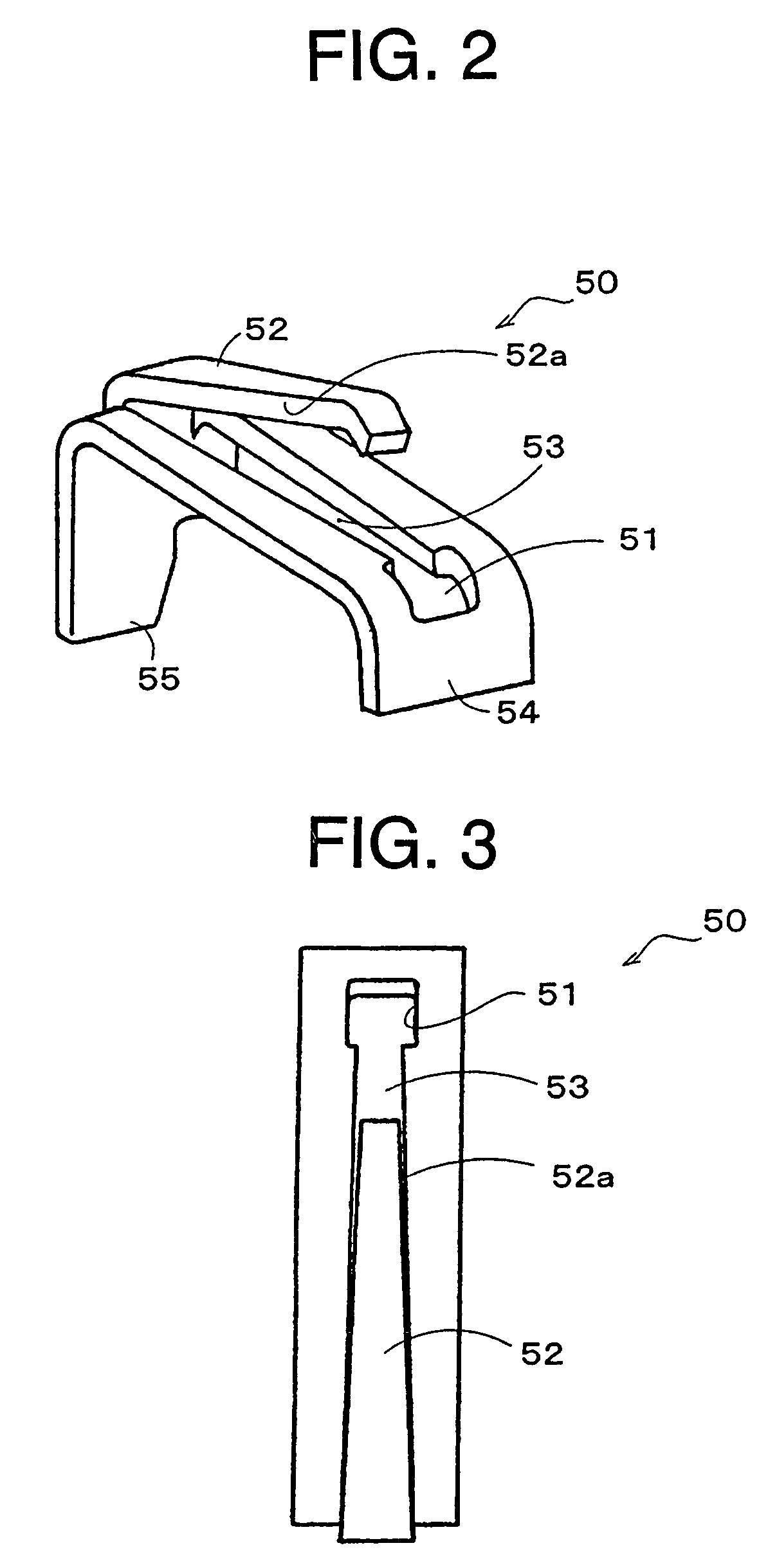
[0059]FIGS. 1 to 7 illustrate a typical first embodiment according to the invention. FIG. 1 is a perspective view showing a state in which parts composing a slider for a slide fastener having an automatic stop function are separated; FIG. 2 is a perspective view showing a spring body composing a portion of the slider; FIG. 3 is a plane view of the spring body; FIG. 4 is a major part longitudinal sectional view showing an assembling order of the slider; FIG. 5 is a major part longitudinal sectional view showing an inner structural example after assembling the slider; FIG. 6 is a perspective view of the slider; and FIG. 7 is an explanatory view showing a state in which locking of the spring body of the slider is released. In the meantime, according to the invention, a shoulder opening side of the slider is referred to as a forward portion and a rear opening side of the slid...


PUM

PropertyMeasurementUnit
Deformation enthalpyaaaaaaaaaa

Abstract

The invention provides a spring body for a slide fastener and a slider having the spring body mounted thereon, comprising: the spring body made of a platy material having an opening window portion at the opposite side of a pawl portion, and entirely formed in a lateral C-shape; a spring piece having a figuration that a longitudinal center portion of the platy material is cut out outward from a side end portion of a main body of the opening window portion to be pulled up at a required height in many steps, disposed between a rear surface of a pull holding body and a pull with elastic contact, and the pawl portion engaged with or released from a portion of a coupling element row by operating the pull through an inside of the slider body. Consequently, it can get the spring body enabling a material and manufacturing cost reduced, a stable and excellent productivity; a slider with an automatic stop function acquiring and realizing inexpensive structure, miniaturization, and simple assembly.

Description

BACKGROUND OF THE INVENTION[0001]1. Field of the Invention[0002]The present invention relates to a spring body for a slide fastener and a slider having the spring body mounted thereon, and particularly, the invention relates to a spring body for a slide fastener and a slider with an automatic stop function having the spring body mounted thereon, whereby the slider is minituarized, the material cost is reduced, and the exterior design is improved.[0003]2. Description of the Related Art[0004]Conventionally, a slider for a slide fastener provided with an automatic stop function is used in many cases, in which the automatic stop function stops the movement of a slider body in such a manner that, by operating a pull against the slider body for coupling and releasing tooth rows of a fastener chain, a pawl portion of a spring body made of a long and minute elastic metal platy material is engaged with a part of the tooth row of the fastener chain. A structural example of such a slider is di...

Claims


Application Information

Patent Timeline
IPC IPC(8): A44B19/30A44B19/26
CPCA44B19/306Y10T24/2561Y10T24/2577Y10T24/2571Y10T24/2566B01D35/00B01D2201/31
Inventor IWASE, YUICHIKEYAKI, KEIICHI
Owner YKK CORP
Why Eureka
Try Eureka