Multi-focal lens for bi-functional headlamp

Inactive Publication Date: 2008-04-15
VARROC LIGHTING SYST SRO
View PDF35 Cites 14 Cited by
  • Summary
  • Abstract
  • Description
  • Claims
  • Application Information

AI Technical Summary

Benefits of technology

[0012]In yet another aspect, when the opaque shield is in the first position, light passing through the first half of the condenser lens does not pass through the first focal point, and therefore is not collimated, and when the opaque shield is in the second position, light reflected from the reflector passes through the second focal point to the second half of the condenser lens and is collimated, thereby creating a high intensity high beam.

Problems solved by technology

The problem associated with this type of headlamp is the need to achieve an ideal balance between low and high beam according to photometrical regulations.

Method used


Image

  • Multi-focal lens for bi-functional headlamp
  • Multi-focal lens for bi-functional headlamp
  • Multi-focal lens for bi-functional headlamp

Examples


Embodiment Construction

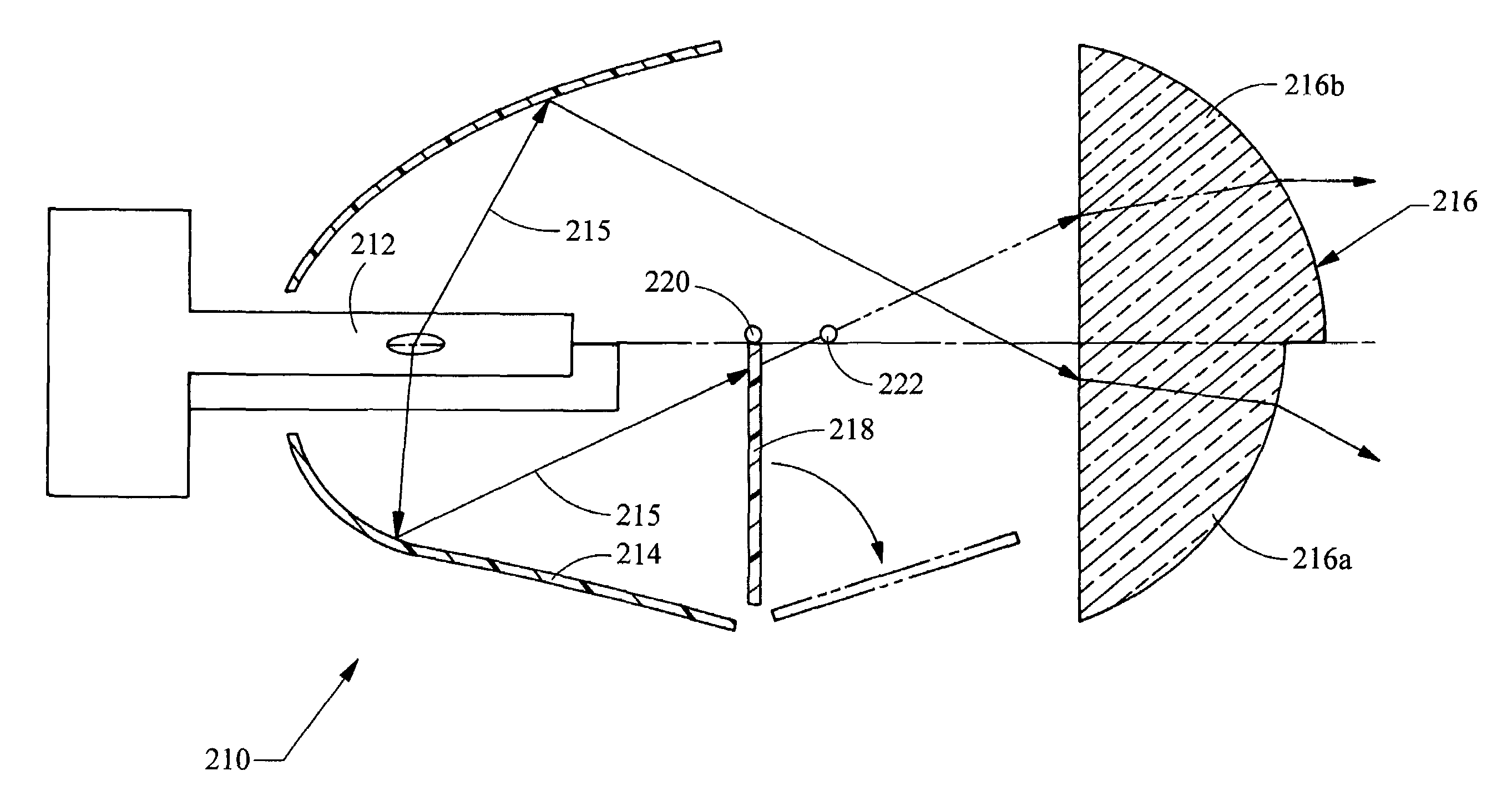
[0017]Referring to FIG. 3, a headlamp assembly in accordance with the present application is shown generally at 210. The headlamp assembly 210 provides both low beam and high beam operation modes and includes a light source 212, a reflector surface 214 adapted to reflect light from the light source outward, as indicated by arrows 215. The light source 212 can be any appropriate light source 212 for use with an automotive headlamp assembly, such as a halogen bulb or HID bulb. A condenser lens 216 is positioned at a distance from the light source 212 such that light 215 from the light source 212 hits the reflector surface 214 and is reflected outward to the condenser lens 216. The condenser lens 216 is adapted to collimate the light 215 passing therethrough.

[0018]An opaque shield 218 is positioned between the light source 212 and the condenser lens 216. The shield 218 is moveable between a first position and a second position. In the first position, a portion of the light 215 reflecte...


PUM


Abstract

The headlamp assembly having low beam and high beam operation modes includes a light source, a reflector surface adapted to reflect light from the light source outward to a condenser lens positioned at a distance from the light source. An opaque shield is positioned between the light source and the condenser lens and is moveable between a first position, where a portion of the reflected light is blocked from reaching the condenser lens, and a second position, where substantially all of the reflected light is allowed to reach the condenser lens. The condenser lens has a first segment and a second segment wherein, when the opaque shield is in the first position, light is reflected almost entirely to the first segment of the condenser lens, and when the opaque shield is in the second position, light is reflected to the first and second segments of the condenser lens.

Description

BACKGROUND[0001]1. Field of the Invention[0002]The invention generally relates to a headlamp assembly having low beam and high beam operation modes and a multi-focal condenser lens.[0003]2. Background of the Invention[0004]Many projector headlamp units have two functions—low beam and high beam. Referring to FIG. 1, a prior art headlamp assembly is generally shown at 10. The headlamp assembly 10 includes a light source 12, a reflector surface 14, and a condenser lens 16. Switching between high beam and low beam is done by a movable shield 18. The shield 18 is moveable between a first position, shown in solid lines, and a second position, shown in dashed lines. In the first position, the shield 18 stops the light 20 reflecting from certain portions of the reflector surface 14 so that this light 20 cannot hit and pass through the condenser lens 16. Thus, the shield 18 creates the cutoff line of the low beam. In the second position, the shield 18 is moved out of the way and allows this ...

Claims


Application Information

Patent Timeline
Patent Type & Authority Patents(United States)
IPC IPC(8): B60Q1/00
CPCF21S48/10F21S48/1258F21S48/1275F21S48/1778F21S41/255F21S41/265F21S41/689F21S41/172F21S41/32F21W2102/13F21S41/162F21S41/00
Inventor STEFKA, JANOLIVIK, MAREKHYNAR, DAVIDKREML, TOMAS
Owner VARROC LIGHTING SYST SRO
Why Eureka
Try Eureka