Limited slip differential and engagement sensing mechanism therefor

a technology of differential and engagement sensing mechanism, which is applied in the direction of differential gearings, belts/chains/gearrings, mechanical instruments, etc., can solve the problems of system utilization that needs to be able to survive and operate effectively, and the arrangement is typically inconvenien

Active Publication Date: 2008-04-15
EATON INTELLIGENT POWER LTD
View PDF10 Cites 24 Cited by
  • Summary
  • Abstract
  • Description
  • Claims
  • Application Information

AI Technical Summary

Benefits of technology

[0011]Accordingly, it is an object of the present invention to provide an improved differential gear mechanism, and an improved sensing mechanism and assembly for use therein, which will overcome the above-described problems of the prior art.

Problems solved by technology

Unfortunately, sensing the occurrence of a locked condition (or an unlocked condition) in a locking differential, or sensing an increasing clutch engagement (or a decreasing clutch engagement) in a limited slip differential involves sensing something such as the axial movement of a member within a differential gear case which, typically, is rotating within a stationary outer housing.
Unfortunately, such an arrangement is typically not feasible.
Another hindrance encountered by those skilled in the art, in attempting to develop arrangements for sensing the “change-of-state” in a limited slip or locking differential is the fact that the sensing system utilized needs to be able to survive and operate effectively in a fairly severe environment.

Method used


Image

  • Limited slip differential and engagement sensing mechanism therefor
  • Limited slip differential and engagement sensing mechanism therefor
  • Limited slip differential and engagement sensing mechanism therefor

Examples


Embodiment Construction

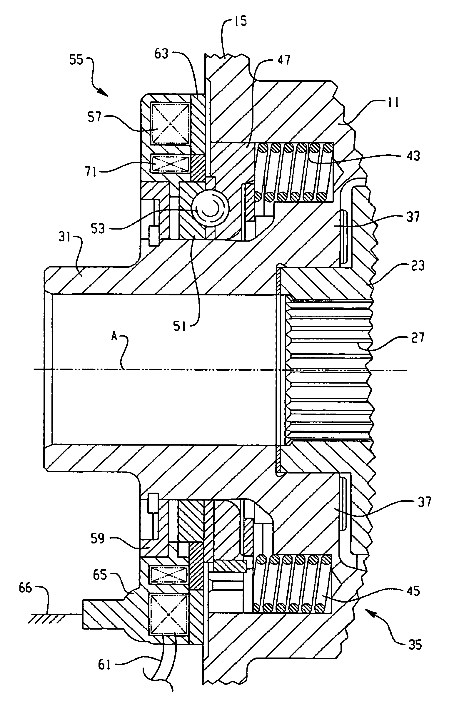
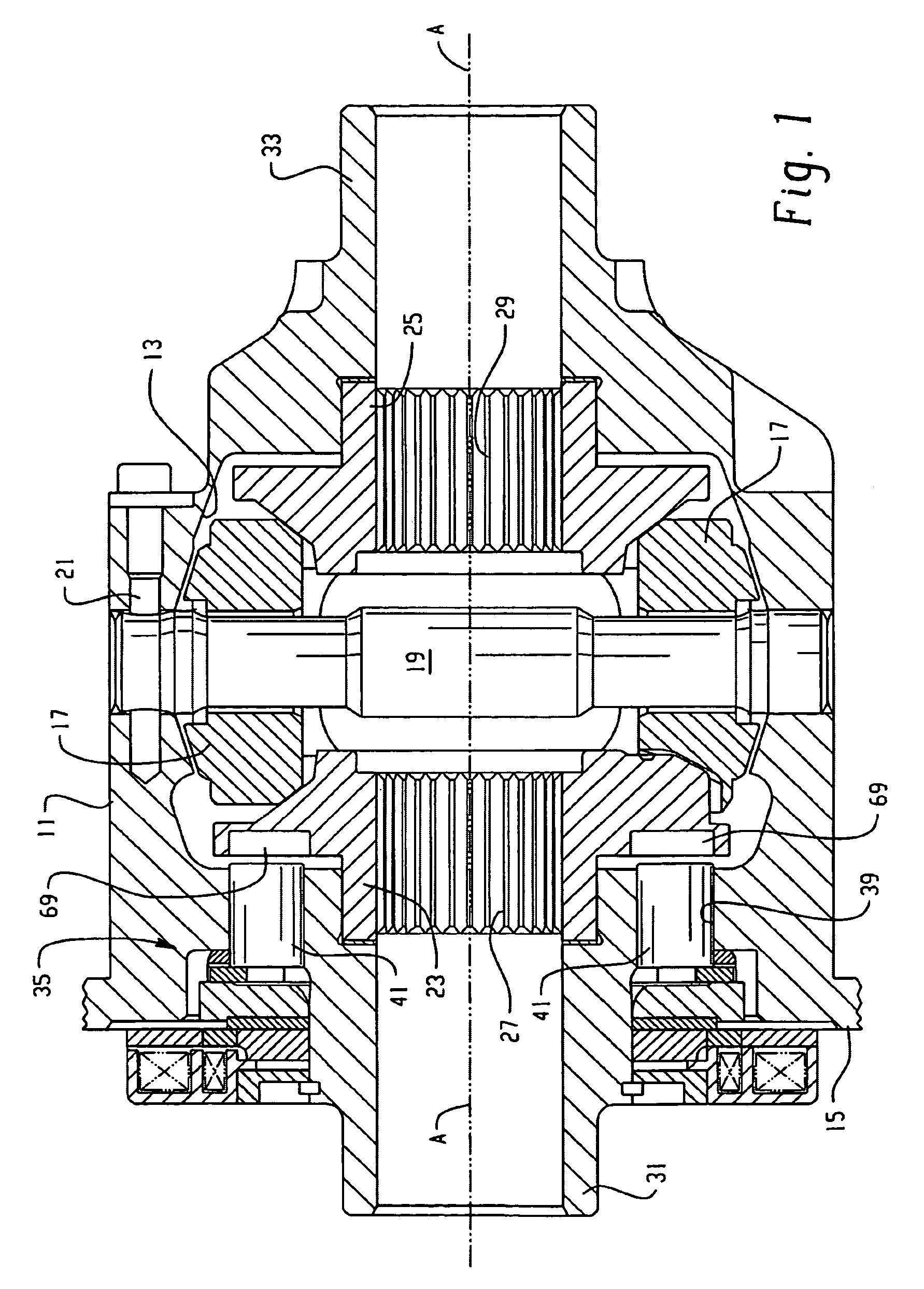
[0024]Referring now to the drawings, which are not intended to limit the invention, FIG. 1 is an axial cross-section of a slip-limiting differential, and more specifically, of a locking differential including the present invention. The specific construction and operation of differentials of the general type to which this invention relates, and of the specific type illustrated in FIG. 1, may be better understood by reference to the above-incorporated patents. Specifically, the overall construction and function of the locking differential shown in FIG. 1 is quite similar to that illustrated and described in above-incorporated U.S. Pat. No. 6,551,209.

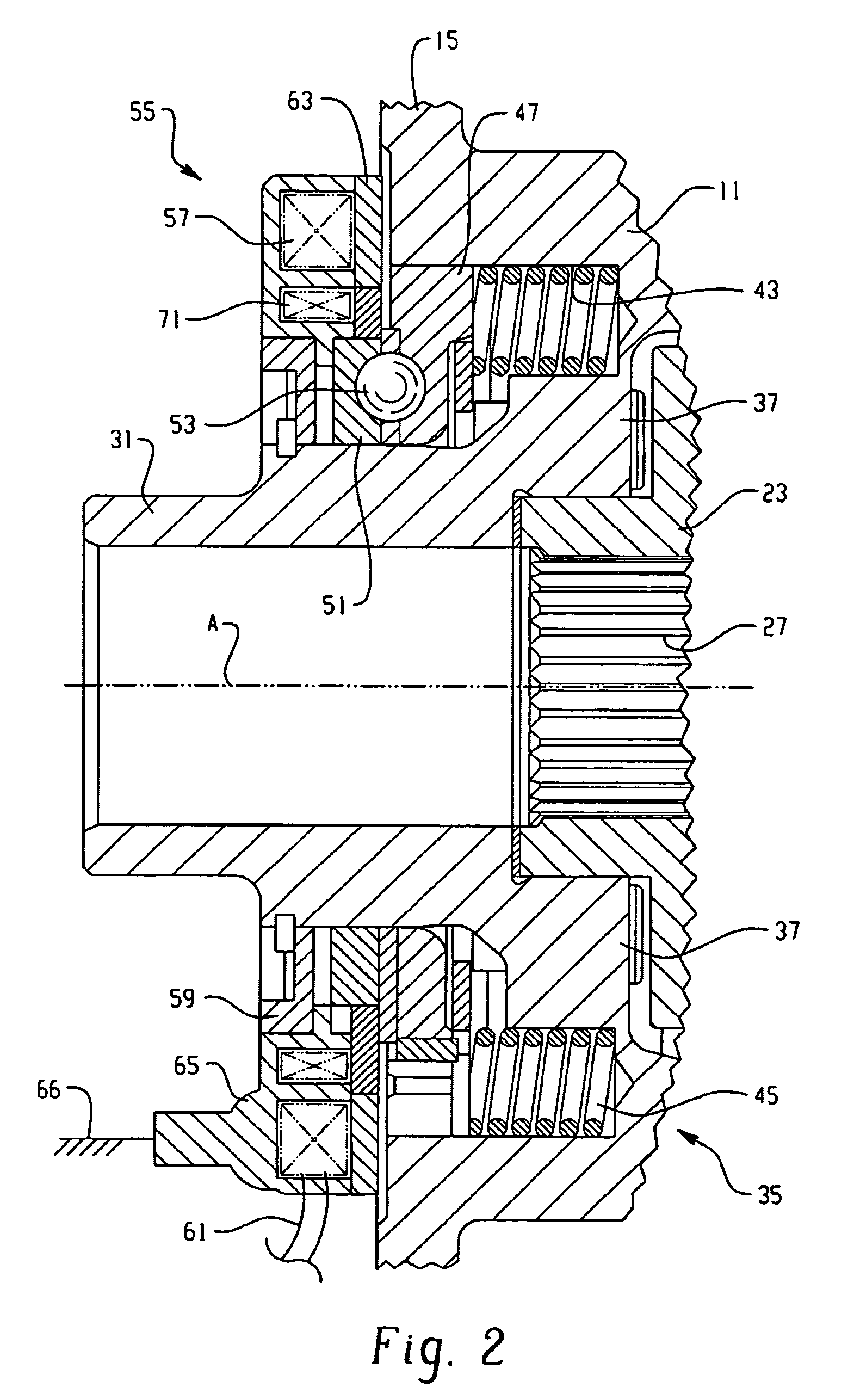
[0025]However, as has already been noted, the usefulness of the present invention is not restricted to only locking differentials, but could be also advantageous when used on limited slip differentials, at least on those including some sort of a member within the differential which moves axially within the differential case such that the m...


PUM


Abstract

A differential having means (35) operable to limit rotation of an output gear (23) relative to a gear case (11), and actuation means (55) for actuating the rotation limiting means, from an unactuated (FIG. 1) to an actuated condition (FIG. 4). The rotation limiting means includes a member (47), toward one axial end of the gear case and moveable between a first position, the unactuated condition of said rotation limiting means, and a second position, the actuated condition. A sensor assembly is adjacent the one axial end of the gear case and includes a sensor element (71) and a wall-like member between the rotation limiting means and the actuation means. The wall-like member includes a non-ferromagnetic portion (73) between the sensor and the moveable member. Movement between the first and second positions results in a corresponding change in the electromagnetic flux (F) coupling the sensor element and the moveable member.

Description

BACKGROUND OF THE DISCLOSURE[0001]The present invention relates to traction modifying differentials, and more particularly, to such differentials of the type in which the differential action may be retarded, and possibly even prevented (“locked”), in response to some sort of an input, for example, a mechanical input or an electrical input signal.[0002]Furthermore, the present invention relates to engagement sensing mechanisms and systems of the type which may be utilized to sense a change-of-state within a traction modifying differential, for example, a change between an unlocked condition and a locked condition.[0003]Traction modifying differentials of the type to which the present invention relates typically include a gear case defining a gear chamber, and disposed therein, a differential gear set including at least one input pinion gear, and a pair of output side gears. The present invention will be described in connection with a differential of the bevel gear type, although thos...

Claims


Application Information

Patent Timeline
Patent Type & Authority Patents(United States)
IPC IPC(8): F16H48/06F16H48/34
CPCF16H48/08F16H48/16F16H48/295F16H48/34F16H48/30F16H48/24F16H2048/346F16H48/40F16H2048/204F16H48/20
Inventor NOFZINGER, SCOTT L.HEATWOLE, GREGORY L.
Owner EATON INTELLIGENT POWER LTD
Why Eureka
Try Eureka