

Power supply control circuit and control method thereof
a power supply control circuit and control circuit technology, applied in the direction of electric variable regulation, process and machine control, instruments, etc., can solve the problems of large rush current flow, large voltage drop in the optical communication apparatus accordingly, and inability to ensure the stable operation of the other modules of the apparatus
- Summary
- Abstract
- Description
- Claims
- Application Information
AI Technical Summary
Benefits of technology
Problems solved by technology
Method used
Image

Examples
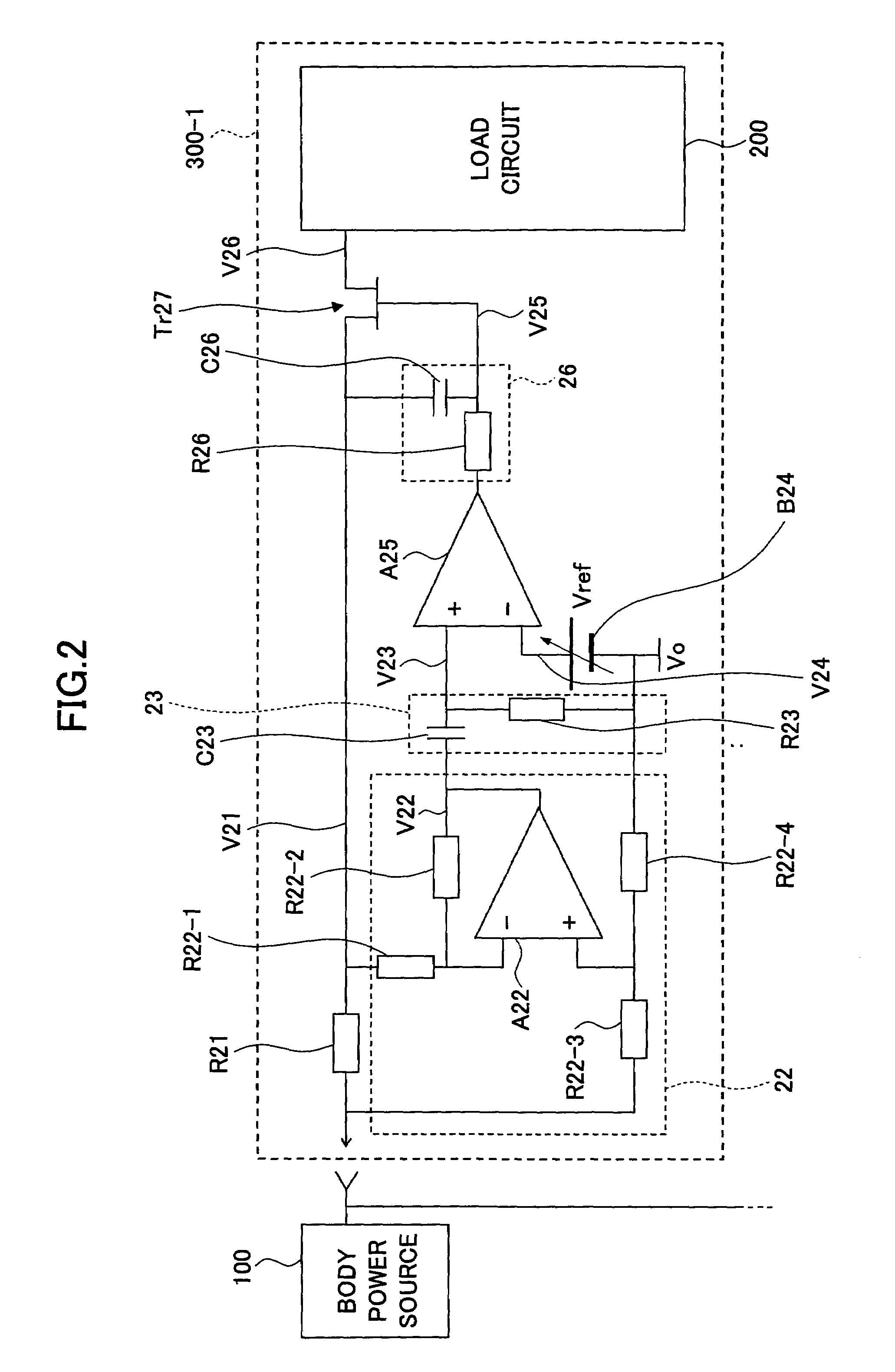
first embodiment
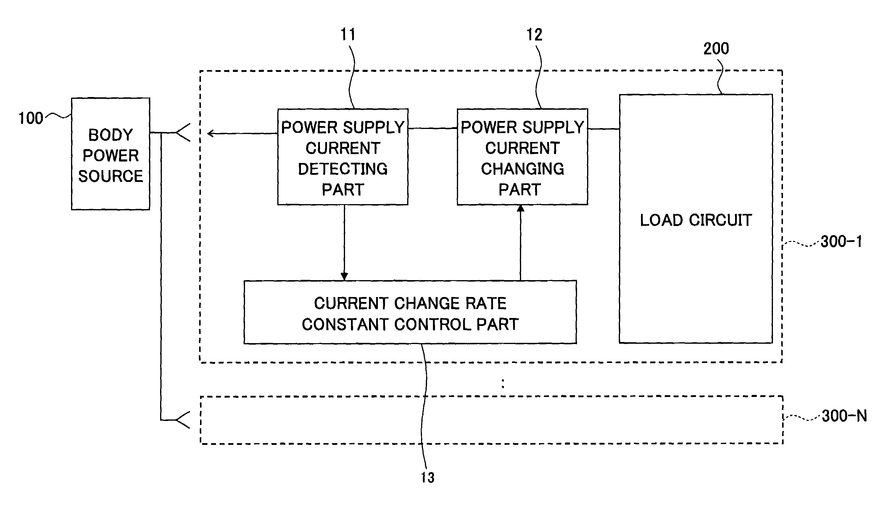
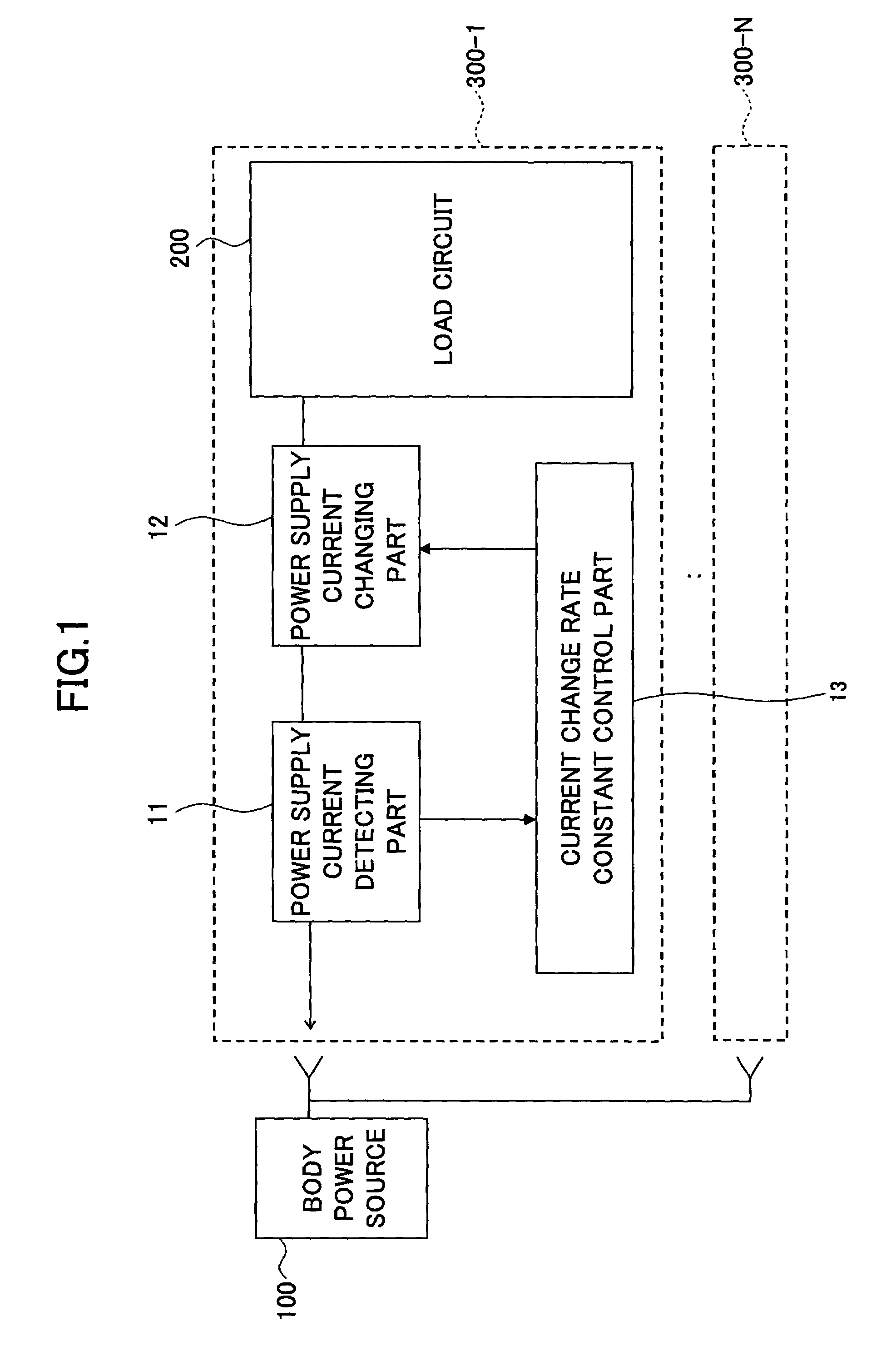
[0033]In a configuration of the present invention described later, a rush current increasing amount upon hot plug insertion of a module can be kept constant by means of a feedback control such as that mentioned above, thus, a variation in a starting-up time required for starting up the module upon hot plug insertion of the module or a variation in the rush current amount can be well controlled, and also, the starting-up time can be effectively reduced.
second embodiment
[0034]Further, in a configuration of the present invention described later, a transformer is applied in a power supply line for the purpose of preventing lowering of a power supply voltage otherwise occurring due to a voltage drop in a resistor, which is inserted in the power supply line for the purpose of detecting a change in the power supply current. Thereby, the lowering of the power supply voltage can be avoided theoretically.
third embodiment
[0035]In a configuration of the present invention described later, a completion of power supply starting-up operation is detected, and an impedance of a circuit connected in parallel to the power supply current detecting resistor is lowered, for the purpose of preventing lowering of the power supply voltage otherwise occurring due to a voltage drop in the resistor, which is inserted in the power supply line for the purpose of detecting a change in the power supply current. Thereby, the lowering of the power supply voltage otherwise occurring due to a voltage drop in the power supply current detecting resistor can be avoided theoretically.
PUM
 Abstract
Description
Claims
Application Information