Spatial light modulator and a display device

a technology of a display device and a light source, which is applied in the field of spatial light source modulators, can solve the problems of occupying a lot of space, increasing the cost, and requiring a separate display screen for each player, and achieves the effect of improving the display quality

Active Publication Date: 2008-04-15
SHARP KK
View PDF18 Cites 64 Cited by
  • Summary
  • Abstract
  • Description
  • Claims
  • Application Information

AI Technical Summary

Benefits of technology

[0040]A further advantage of providing the first and second electrode layers at different spacings from the first substrate is that it allows the gap between adjacent addressable regions in U.S. Pat. No. 6,049,424, arising from the gap 23 between neighbouring electrodes, to be eliminated. By eliminating the unaddressed regions of the liquid crystal layer in the SLM of U.S. Pat. No. 6,049,424, the transmissive gaps in the opaque regions 14 of a parallax barrier defined in the SLM are consequently eliminated. When an SLM of this embodiment is used to provide the parallax barrier in a multiple view display, it can provide a reconfigurable parallax barrier that allows the positions of the viewing windows to be changed in accordance with the position of an observer to provide observer tracking; however, the elimination of the transmissive gaps in the opaque regions 14 of the parallax barrier avoids cross-talk between the two images and improves the display quality.

Problems solved by technology

These conflicting needs could be satisfied by providing two separate display devices, but this would take up extra space and would increase the cost.
Furthermore, if two separate displays were used in this example it would be possible for the driver to see the passenger's display if the driver moved his or her head, which would be distracting for the driver.
However, providing a separate display screen for each player takes up a lot of space and is costly, and is not practical for portable games.
However, the two images displayed on an autostereoscopic display are the left-eye and right-eye images of a stereoscopic image pair, and so are not independent from one another.
The display is said to have low “viewing freedom”.
While this may not be of consequence in, for example, a motor vehicle where the occupants have only limited freedom to move, it is a significant problem in some possible applications of a dual view display.
However, this introduces moving parts and so leads to wear and unreliability; the mechanism for translating the barrier also adds weight and bulk to the display.
However, this can be difficult to achieve with many common LC modes.
The method of U.S. Pat. No. 6,049,424 has the disadvantage that there is necessarily a gap 23 between adjacent electrodes; these gaps are typically 10 μm wide, and each gap 23 will lead to a corresponding region of the liquid crystal layer that is not addressed.
Moreover, each electrode Ei must be individually addressed, and this requires expensive drive circuitry.

Method used


Image

  • Spatial light modulator and a display device
  • Spatial light modulator and a display device
  • Spatial light modulator and a display device

Examples


Embodiment Construction

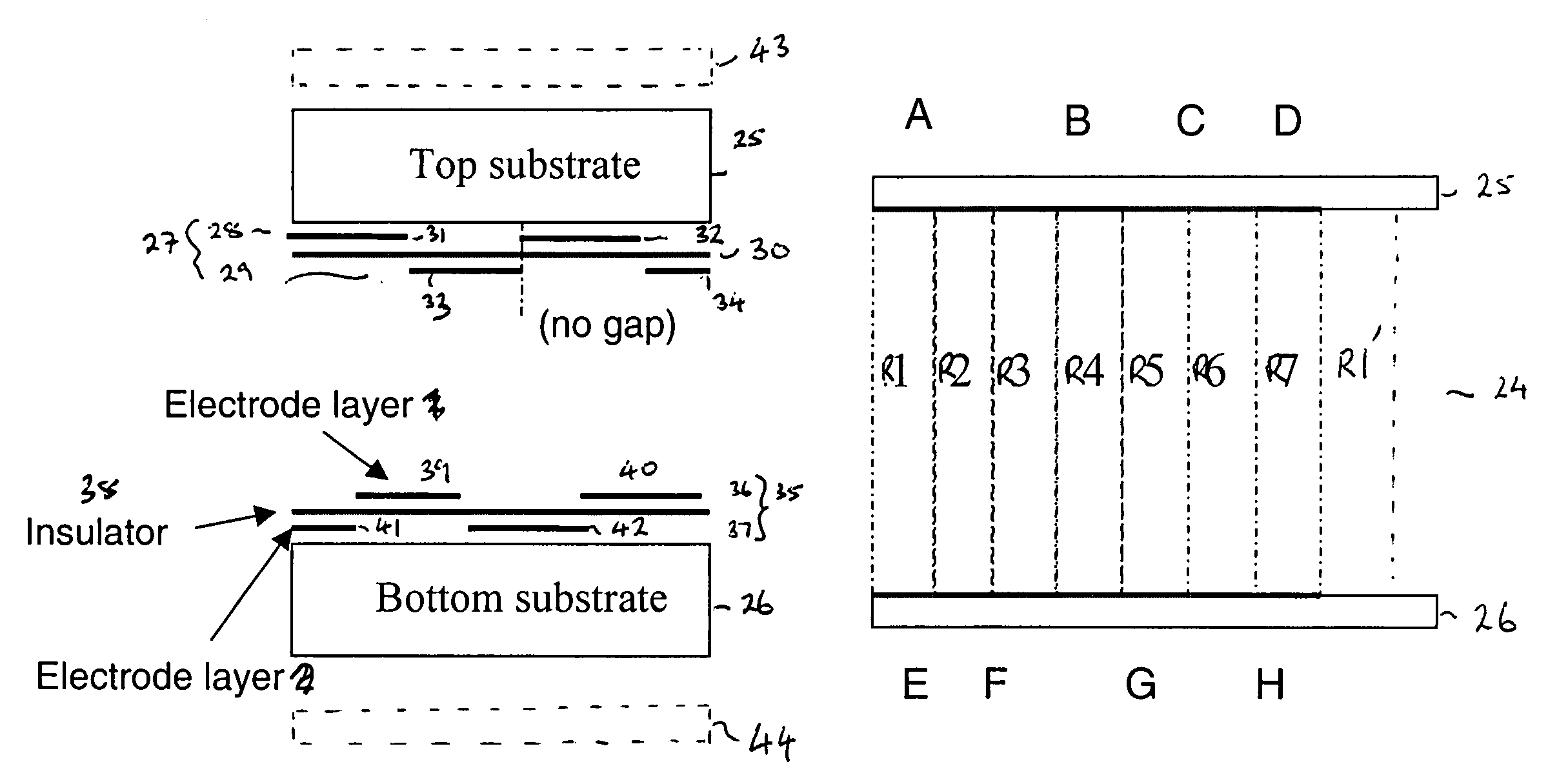
[0073]In a spatial light modulator (SLM) of the present invention, a layer of electrooptic material is addressed by means of a first electrode arrangement and second electrode arrangement. The first and second electrode arrangements are configured so as to define a plurality of addressable regions in the electrooptic material. This enables a reconfigurable parallax barrier to be defined in the SLM, by driving some of the addressable regions to be opaque while driving other of the addressable regions to be transmissive. The parallax barrier may be reconfigured by re-selecting those addressable regions which are driven to be opaque and those regions which are driven to be transmissive, as in U.S. Pat. No. 6,049,424. The layer of electrooptic material may be, for example, a layer of liquid crystal material.

[0074]In the present invention, the addressable regions are preferably defined in the electrooptic material such that an addressable region is at least contiguous with a neighbouring...


PUM

PropertyMeasurementUnit
widthaaaaaaaaaa
frequencyaaaaaaaaaa
thicknessaaaaaaaaaa

Abstract

A spatial light modulator comprises: a first substrate (25); a second substrate (26); a layer of electrooptic material disposed between the first substrate and the second substrate. A first electrode arrangement (27) is disposed over the first substrate (25); and a second electrode arrangement (35) is disposed over the second substrate (26). The first electrode arrangement (27) comprises first and second electrode layers (28,29) disposed over the first substrate, with the spacing between the first electrode layer (28) and the first substrate (25) being different to the spacing between the second electrode (29) layer and the first substrate (25). The first electrode layer (28) and the second electrode arrangement (35) are configured so as to co-operate, in use, to define a plurality of first addressable regions in the electrooptic material. The second electrode (29) layer and the second electrode arrangement (35) are configured so as to co-operate, in use, to define a plurality of second addressable regions in the electrooptic material.

Description

FIELD OF THE INVENTION[0001]The present invention relates to a spatial light modulator, and in particular to a spatial light modulator suitable for use as a parallax optic in multiple-view directional display which displays two or more images such that each image is visible from a different direction. It also relates to a display device incorporating a spatial light modulator of the inventionBACKGROUND OF THE INVENTION[0002]For many years conventional display devices have been designed to be viewed by multiple users simultaneously. The display properties of the display device are made such that viewers can see the same good image quality from different angles with respect to the display. This is effective in applications where many users require the same information from the display—such as, for example, displays of departure information at airports and railway stations. However, there are many applications where it would be desirable for individual users to be able to see different...

Claims


Application Information

Patent Timeline
Patent Type & Authority Patents(United States)
IPC IPC(8): G02F1/03G02F1/133G02F1/1339G02F1/1343G09G3/18G09G3/36G02B30/31
CPCG02F1/1323G02F1/134309G02B27/2214H04N13/0411H04N13/0413H04N13/0447H04N13/0409G02F2201/124H04N13/312H04N13/31H04N13/315H04N13/351G02B30/31G02B30/27
Inventor JACOBS, ADRIAN MARC SIMONKEAN, DIANA ULRICHMONTGOMERY, DAVID JAMES
Owner SHARP KK
Why Eureka
Try Eureka