
Load balancing with mesh tagging

a load balancing and mesh technology, applied in the field of communication networks, can solve problems such as complex computing networks

Active Publication Date: 2008-04-15
HEWLETT-PACKARD ENTERPRISE DEV LP
View PDF15 Cites 20 Cited by
  • Summary
  • Abstract
  • Description
  • Claims
  • Application Information

AI Technical Summary

Benefits of technology

This approach enhances load balancing by efficiently distributing traffic across multiple paths, reducing latency and improving network performance by utilizing all available paths and prioritizing high-capacity paths for critical traffic streams.

Problems solved by technology

Computing networks are therefore complex and vary in their configurations and topologies.
For example, the financial department of a large corporation may have significant information exchange requirements within the financial department but comparatively insignificant needs for data exchange with other departments.
Where there is but a single path connecting two network devices, that single path, including all intermediate devices between the source and destination devices, represent a single point of failure in network communications between that source and destination device.

Method used


Image

  • Load balancing with mesh tagging
  • Load balancing with mesh tagging
  • Load balancing with mesh tagging

Examples


Embodiment Construction

A. Switching Mesh and Path Tagging

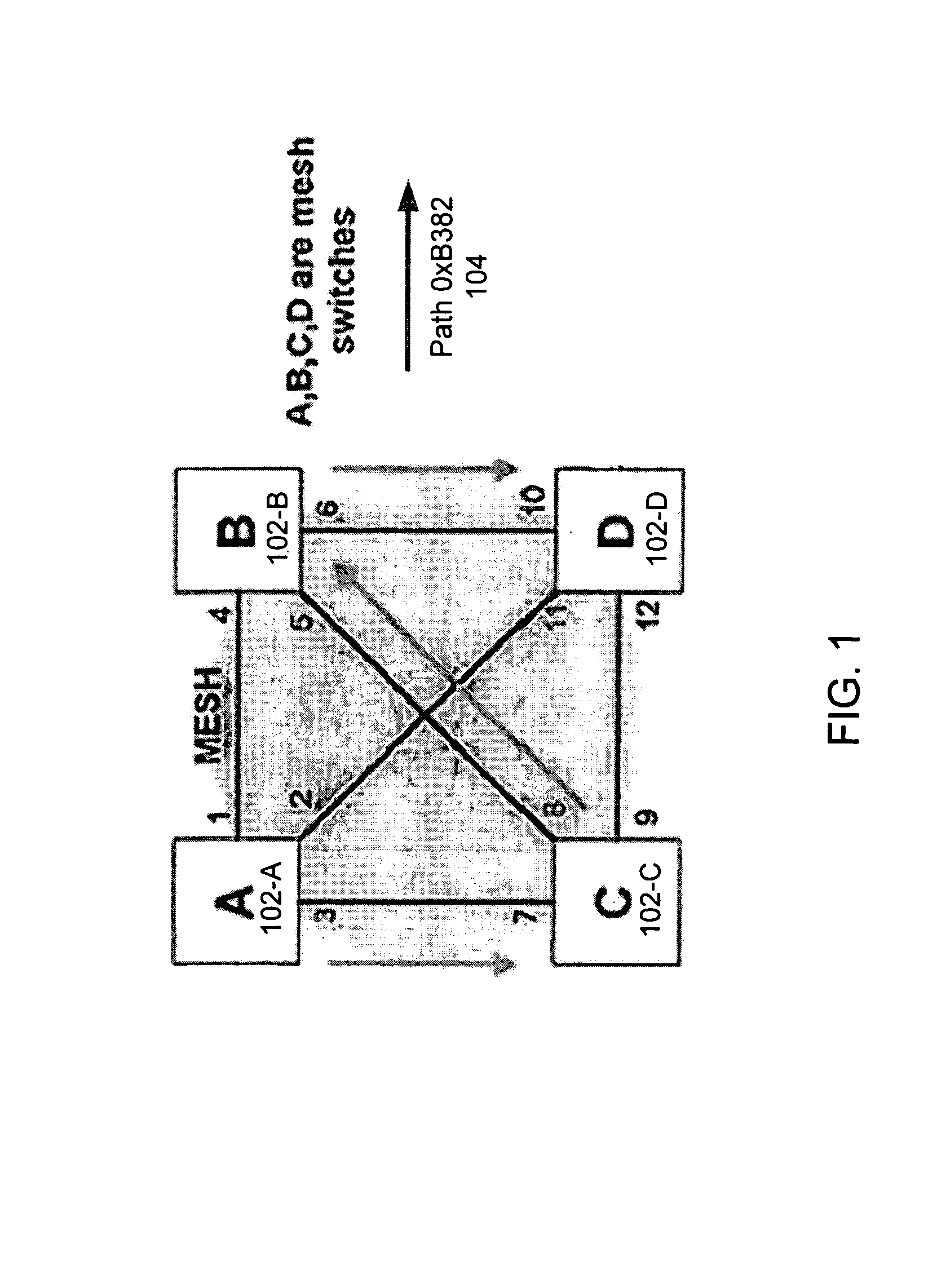
[0028]FIG. 1 is a schematic diagram depicting a switching mesh in accordance with an embodiment of the invention. One example path 104 is shown in FIG. 1. This path 104, designated in this instance as path 0xB382, travels as follows: exits port 3 of switch A 102-A; enters port 7 of switch C 102-C; exits port 8 of switch C 102-C; enters port 5 of switch B 102-B; exits port 6 of switch B 102-B; and enters port 10 of switch D 102-D.

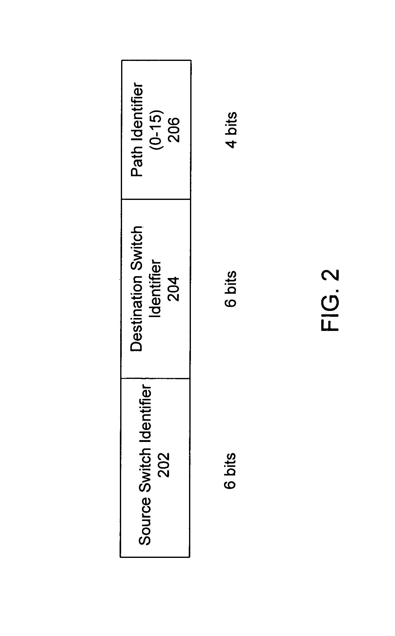
[0029]In accordance with an embodiment of the invention, mesh tagging is utilized to advantageously identify paths within the mesh from a source switch to a destination switch. In one implementation, each source / destination pair may be configured with up to fifteen different paths. This is because four bits are used for the path identifier in a path tag and the zero value is considered invalid in this specific implementation. One example of such a path tag is described further below in relation to FIG. 2. Other embodiments m...


PUM


Abstract

One embodiment disclosed relates to a method of load balancing traffic in a switching mesh. A packet is received at a switch of the mesh. A MAC destination address is gathered from the packet. An entry in a MAC address table is found with the MAC destination address, and a switch identifier associated with the MAC destination address is obtained. An entry in a switch table is found with the switch identifier, and data associated with the switch identifier is obtained. A hash function is used on field data from the packet to generate a hash value, and the hash value and the associated data are used to generate an index value. An entry in the tag table is found with the index value, and a path tag associated with the index value is obtained. The path tag is inserted into the packet. The path tags may be weighted.

Description

BACKGROUND OF THE INVENTION[0001]1. Field of the Invention[0002]The present invention relates generally to communication networks. More specifically, the present invention relates to network switches and switch-to-switch protocols.[0003]2. Description of the Background Art[0004]It is common in conventional computing environments to connect a plurality of computing systems and devices through a communication medium often referred to as a network. Such networks among communicating devices permit devices (or users of devices) to easily exchange and share information among the various devices. The Internet is a presently popular example of such networking on a global scale. Individual users attach their computers to the Internet, thereby enabling sharing of vast quantities of data on other computers geographically dispersed throughout the world.[0005]Networked computing systems may be configured and graphically depicted in a wide variety of common topologies. In other words, the particu...

Claims


Application Information

Patent Timeline
Patent Type & Authority Patents(United States)
IPC IPC(8): H04L12/28H04L1/00H04L12/56H04J1/16H04J3/14
CPCH04L12/5695H04L45/20H04L45/22H04L45/28H04L45/302H04L45/745H04L47/10H04L47/125H04L49/103H04L49/15H04L49/201H04L49/25H04L47/70
Inventor WAKUMOTO, SHAUN KAZUOBARE, BALLARD CLAUDEERSOY, CETIN
Owner HEWLETT-PACKARD ENTERPRISE DEV LP
Learn More