Method and apparatus for determining camera pose from point correspondences

a technology of camera pose and correspondence, applied in the field of method and apparatus for determining camera pose from point correspondence, can solve the problem that uncalibrated methods are often failures, and achieve the effect of reducing the cost function

Active Publication Date: 2008-04-15
SRI INTERNATIONAL
View PDF12 Cites 32 Cited by
  • Summary
  • Abstract
  • Description
  • Claims
  • Application Information

AI Technical Summary

Benefits of technology

[0006]In one embodiment, the method presented in this specification provides a better elimination that leads directly to the tenth degree polynomial. Thus, an efficient method that corresponds exactly to the intrinsic degree of difficu

Problems solved by technology

Thus, uncalibrated methods will often fail when faced with coplanar

Method used


Image

  • Method and apparatus for determining camera pose from point correspondences
  • Method and apparatus for determining camera pose from point correspondences
  • Method and apparatus for determining camera pose from point correspondences

Examples


Embodiment Construction

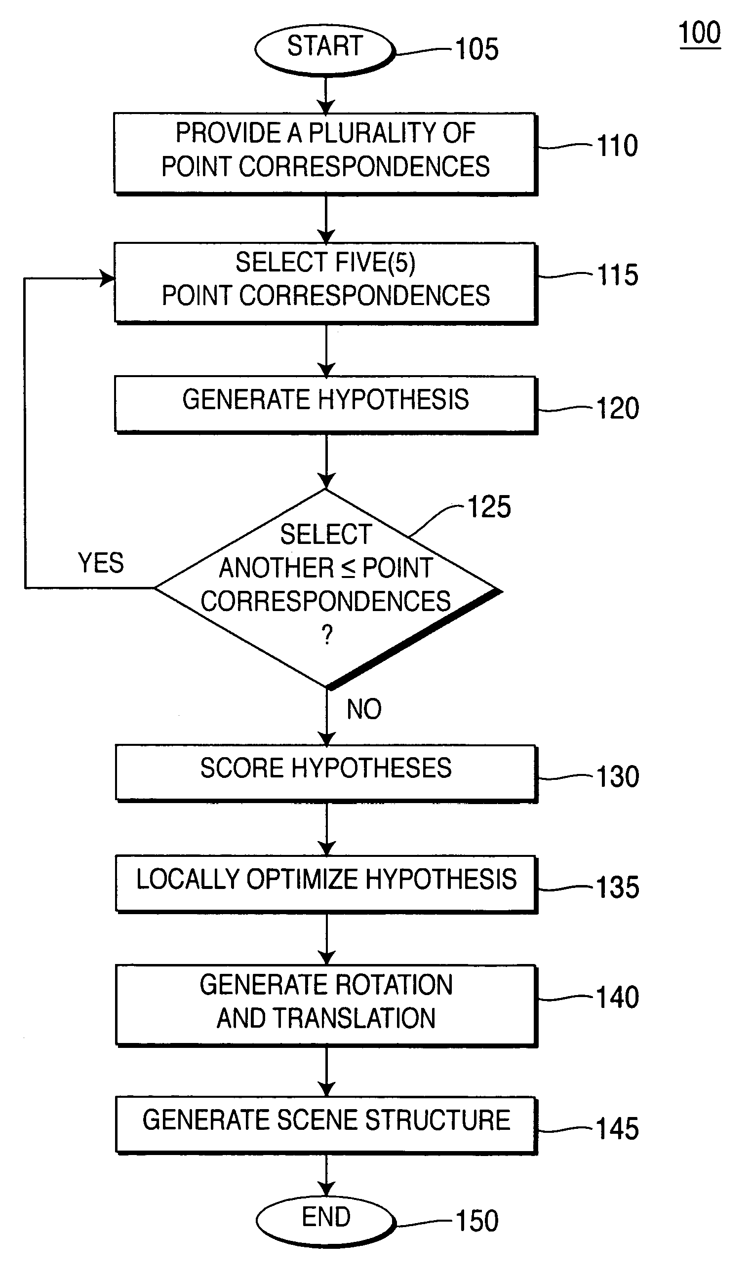
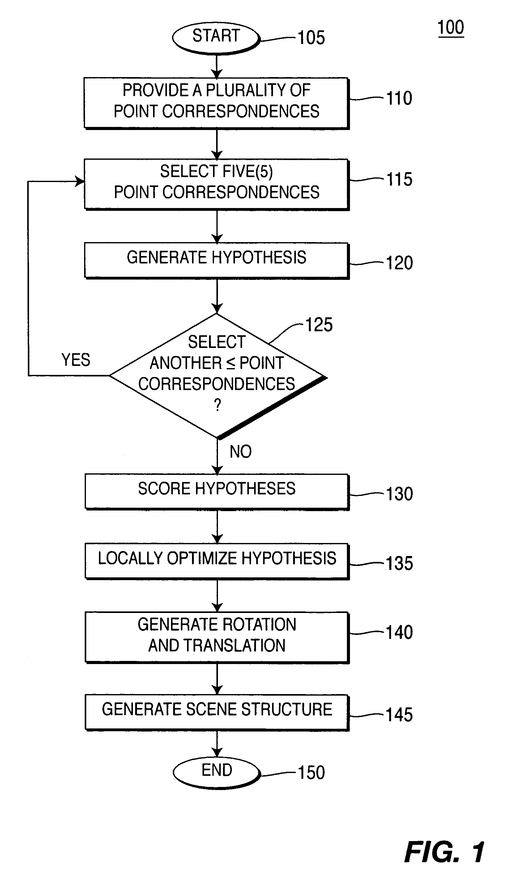
[0020]FIG. 1 illustrates a flowchart of a method 100 for generating solutions to camera motion and scene structure from a plurality of images. FIG. 1 illustrates the present invention in broad steps, where each step will be further disclosed below. Method 100 starts in step 105 and proceeds to step 110.

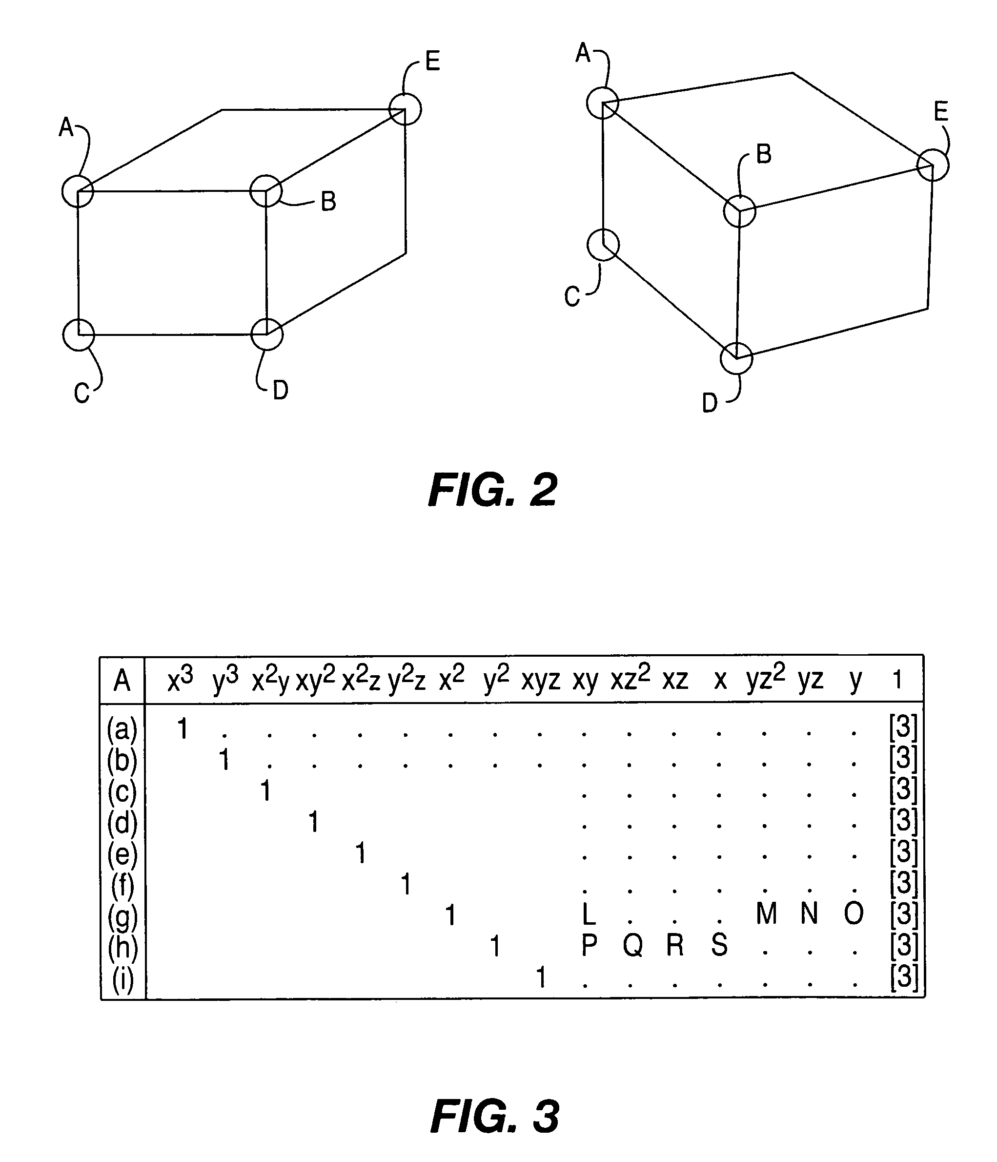
[0021]In step 110, a plurality of point correspondences are provided between at least two images. In other words, pairs of image points within a scene are identified between two images of the same scene. For example, FIG. 2 illustrates an example of a set of 5 point correspondences of a scene. If two images showing a scene containing a wooden crate that is taken from two different camera views, then corresponding corners A-E of the wooded crates are considered a set of 5 point correspondences of a scene. Of course, this scene contains many point correspondences that are not specifically labeled. In practice, the point correspondences can be identified using an automatic feature matche...


PUM


Abstract

A method and apparatus for determining camera pose from point correspondences. Specifically, an efficient solution to the classical five-point relative pose problem is presented. The problem is to find the possible solutions for relative camera motion between two calibrated views given five corresponding points. The method consists of computing the coefficients of a tenth degree polynomial and subsequently finding its roots. The method is well suited for numerical implementation that also corresponds to the inherent complexity of the problem. The method is used in a robust hypothesize- and-test framework to estimate structure and motion in real-time.

Description

[0001]This application claims the benefit of U.S. Provisional Application No. 60 / 453,625 filed on Mar. 11, 2003 and No. 60 / 503,332 filed on Sep. 16, 2003, which are herein incorporated by reference.[0002]The present invention relates to a novel method and apparatus for image processing. Specifically, the present invention provides an efficient, general and robust method for determination of the relative viewpoints of calibrated cameras by analysis of 5-tuples of corresponding image points across two (2) or more image or video frames.[0003]This invention was made with U.S. government support under U.S. Army contract number DAAD19-01-2-0012. The U.S. government has certain rights in this invention.BACKGROUND OF THE INVENTIONField of the Invention[0004]Reconstruction of camera positions and scene structure based on images of scene features from multiple viewpoints has been studied for over two centuries, first by the photogrammetry community and more recently in computer vision. The fi...

Claims


Application Information

Patent Timeline
IPC IPC(8): G06K9/00G06K9/32G06TG06T7/00G06V10/147G06V10/24H04N5/225
CPCG06K9/209G06K9/32G06T7/004G06T2207/30244G06T7/70G06V10/147G06V10/24
Inventor NISTER, DAVID
Owner SRI INTERNATIONAL
Why Eureka
Try Eureka