Image-detectable monitoring system and method for using the same

a monitoring system and image technology, applied in the field of image detection monitoring system and a method for using the same, can solve the problems of difficult to identify the face, the fixed monitoring camera to rotate beyond the fixed direction, and the difficulty in precisely identifying the subject within the image, so as to achieve the effect of easy search

Active Publication Date: 2008-04-15
HANWHA VISION CO LTD
View PDF10 Cites 50 Cited by
  • Summary
  • Abstract
  • Description
  • Claims
  • Application Information

AI Technical Summary

Benefits of technology

[0015]The system scans for candidate areas and once found, directs the capture of enlarged images. If a facial image is detected in these enlarged images, the enlar...

Problems solved by technology

It is impossible however, for the fixed monitoring camera to rotate beyond the fixed direction, therefore it captures images only for a specific spot at the installed position, and often covers and captures images within a wide area rather than a specific, or more narrow part of the monitoring spot.
Accordingly, a video signal for the wide area of a monitoring spot has lesser image quality when compared to a video signal taken for a specific part of the monitoring spot, causing difficulties in exactly identifying a subject within the image.
That is, since the monitoring camera cap...

Method used


Image

  • Image-detectable monitoring system and method for using the same
  • Image-detectable monitoring system and method for using the same
  • Image-detectable monitoring system and method for using the same

Examples


Embodiment Construction

[0021]Hereinafter, the present invention will be described in detail with reference to the attached drawings.

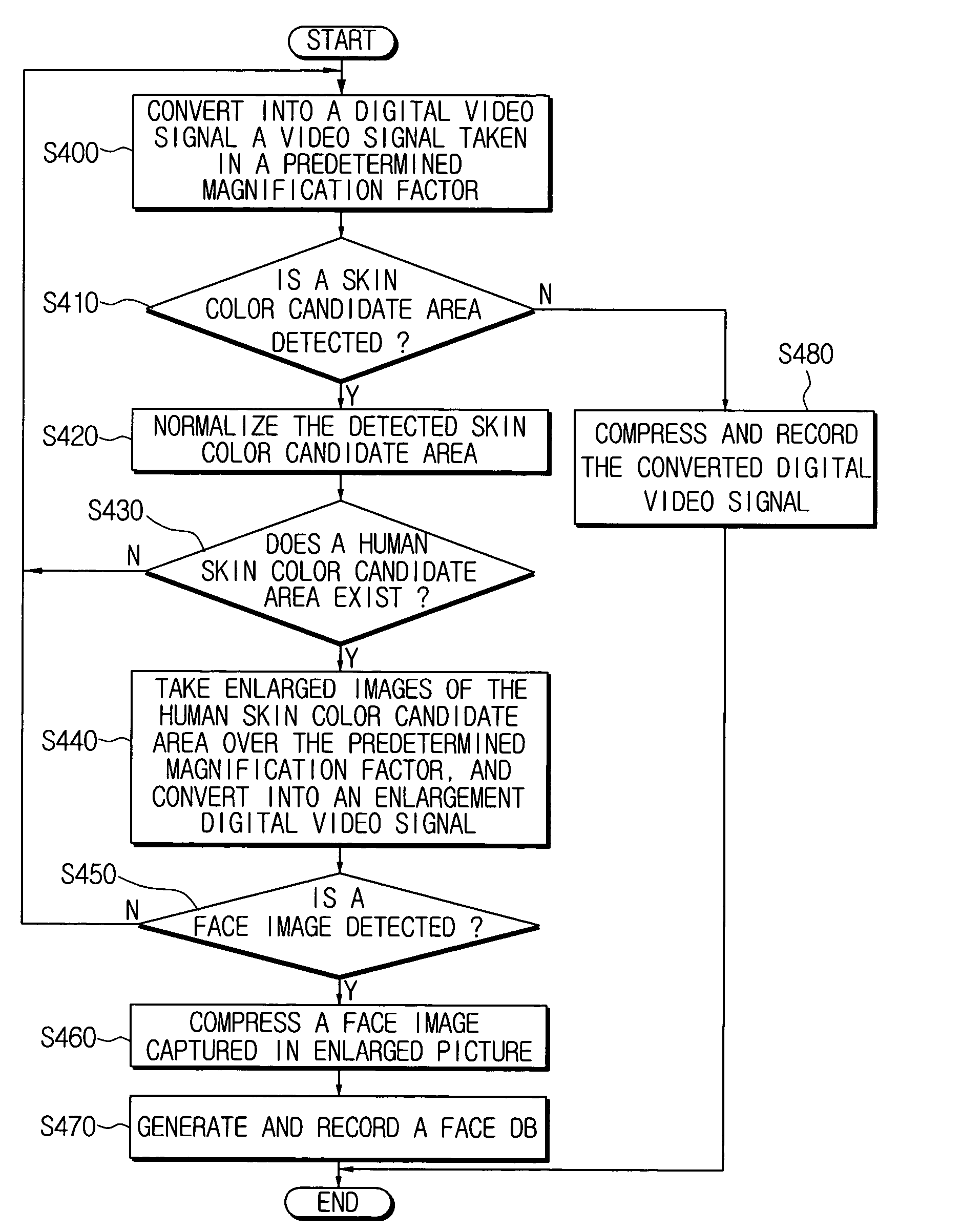
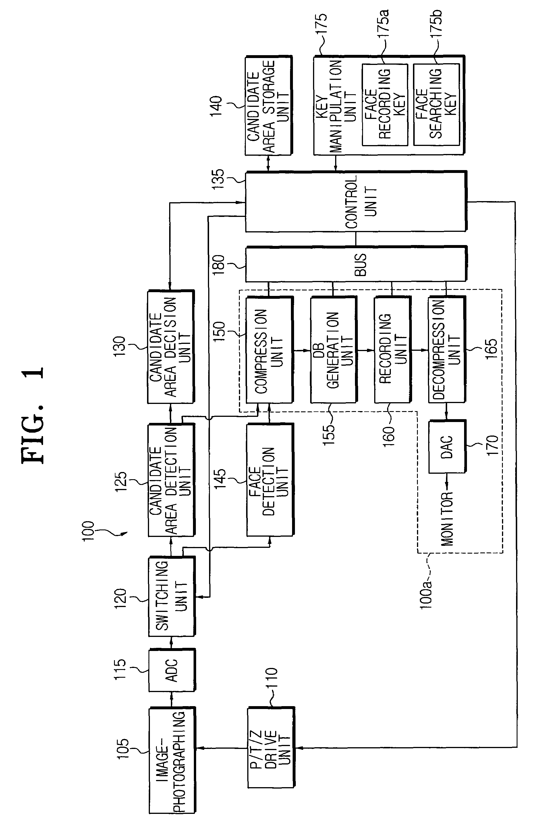
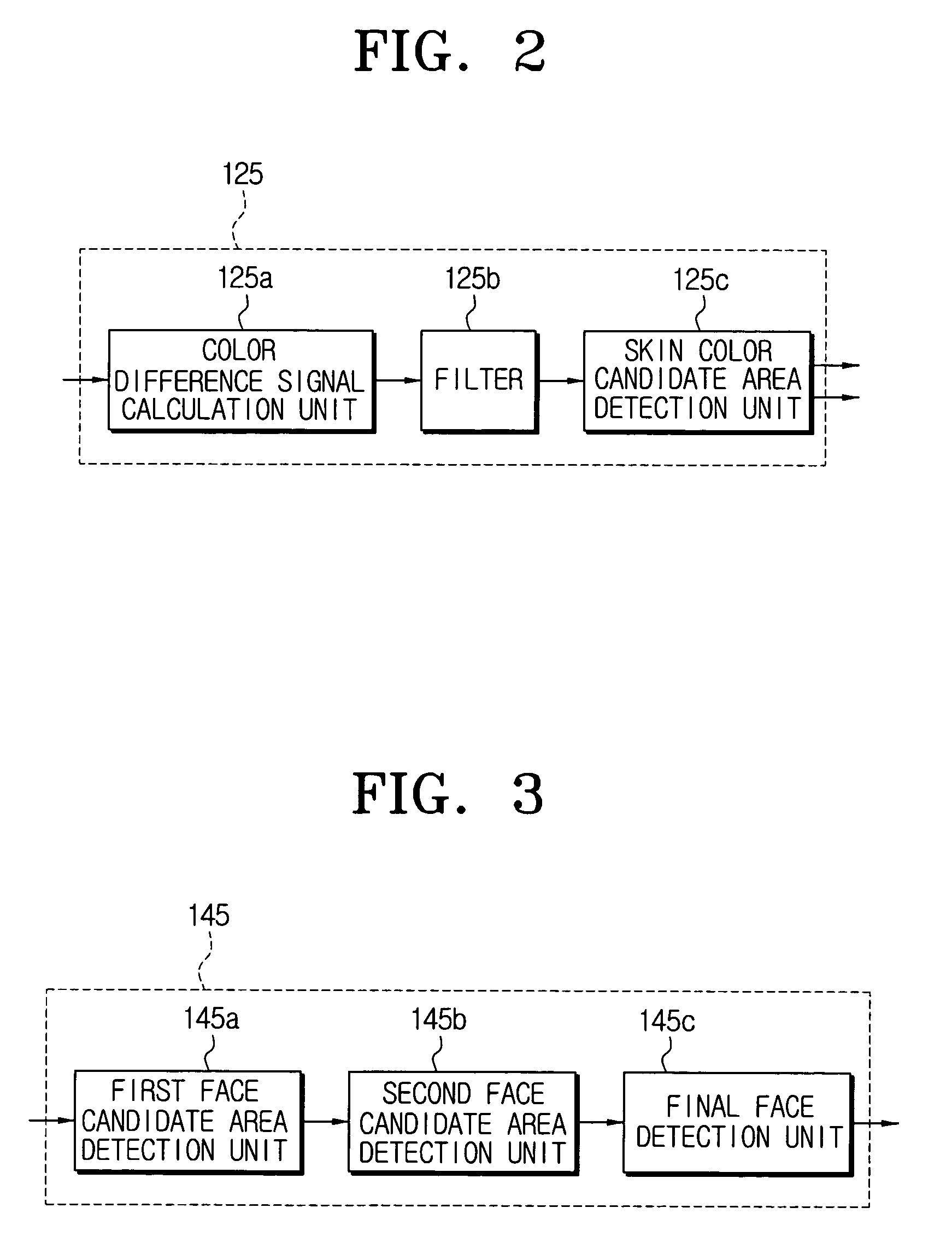
[0022]FIG. 1 is a block diagram showing an example of a facial image monitoring system according to an embodiment of the present invention, FIG. 2 is a block diagram showing an example of a candidate area detection unit of FIG. 1 in detail, and FIG. 3 is a block diagram showing an example of a face detection unit of FIG. 1 in detail.

[0023]Referring to FIG. 1, an example of face image monitoring system 100 according to an embodiment of the present invention has a image-photographing unit 105, a pan / tilt / zoom drive unit (hereinafter, referred to as “P / T / Z drive unit”) 110, an analog / digital conversion unit (hereinafter, referred to as “ADC”) 115, a switching unit 120, a candidate area detection unit 125, a candidate area decision unit 130, a control unit 135, a candidate area storage unit 140, a face detection unit 145, a compression unit 150, a database (hereinafter, referred ...


PUM


Abstract

A monitoring system and method is provided that can detect and capture an image at a monitored position as an analog video signal, and in response, convert the analog video signal into a digital video signal for enlargement, analysis and storage of detected facial images therein. The system includes a candidate area detection unit for comparing a color difference signal level of the converted digital video signal with a reference range, a control unit for outputting a zooming control signal and a face detection unit for detecting a face video signal from the enlarged images. A compression/recording unit is provided for then compressing and recording the detected face image video signal, and allowing a user to easily perform a search for a subject's face when searching recorded video data.

Description

CROSS-REFERENCE TO RELATED APPLICATIONS[0001]This application claims the benefit of Korean Patent Application No. 2003-23791, filed Apr. 15, 2003 and Korean Patent Application No. 2003-14105, filed Mar. 6, 2003, in the Korean Intellectual Property Office, the disclosure of which is incorporated herein by reference.BACKGROUND OF THE INVENTION[0002]1. Field of the Invention[0003]The present invention relates to an image-detectable monitoring system and a method for using the same, and more particularly, to a human face image-detectable monitoring system and method that is capable of detecting, enlarging, and capturing a subjects' facial images, compressing the images for records and storage, and thereafter allowing searching and retrieving of the compressed and recorded images.[0004]2. Description of the Related Art[0005]The next generation closed-circuit TV (CCTV) system is a monitoring system having at least one monitoring camera installed at monitoring spots where security is requi...

Claims


Application Information

Patent Timeline
IPC IPC(8): G06K9/00G06K9/62
CPCG06K9/00228G06K9/6232G06V40/161G06V10/7715G06F18/213
Inventor LEE, HYEOK-BEOM
Owner HANWHA VISION CO LTD
Why Eureka
Try Eureka