Electricity metering with a current transformer

a current transformer and metering technology, applied in the direction of instruments, effective value measurements, transmission systems, etc., can solve the problems of reducing the accuracy of the reading produced by the meter, the actual transformer is not ideal, and the load current sensing is more problemati

Active Publication Date: 2008-04-15
VERIS INDS
View PDF7 Cites 74 Cited by
  • Summary
  • Abstract
  • Description
  • Claims
  • Application Information

AI Technical Summary

Problems solved by technology

Load current sensing is more problematic, but is commonly performed with a current transformer.
However, actual transformers are not ideal transformers and the magnetization of the core of the current transformer produces errors that reduce the accuracy of the readings produced by the meter.
Current transformer error comprises a phase error and a ratio error.
However, the phase and ratio errors vary with the burden and the magnitude of the primary current.
In addition, the error correction factors are generated from a sample of a particular transformer configuration and are not necessarily representative and accurate for a specific transformer used in a particular meter.

Method used


Image

  • Electricity metering with a current transformer
  • Electricity metering with a current transformer
  • Electricity metering with a current transformer

Examples


Embodiment Construction

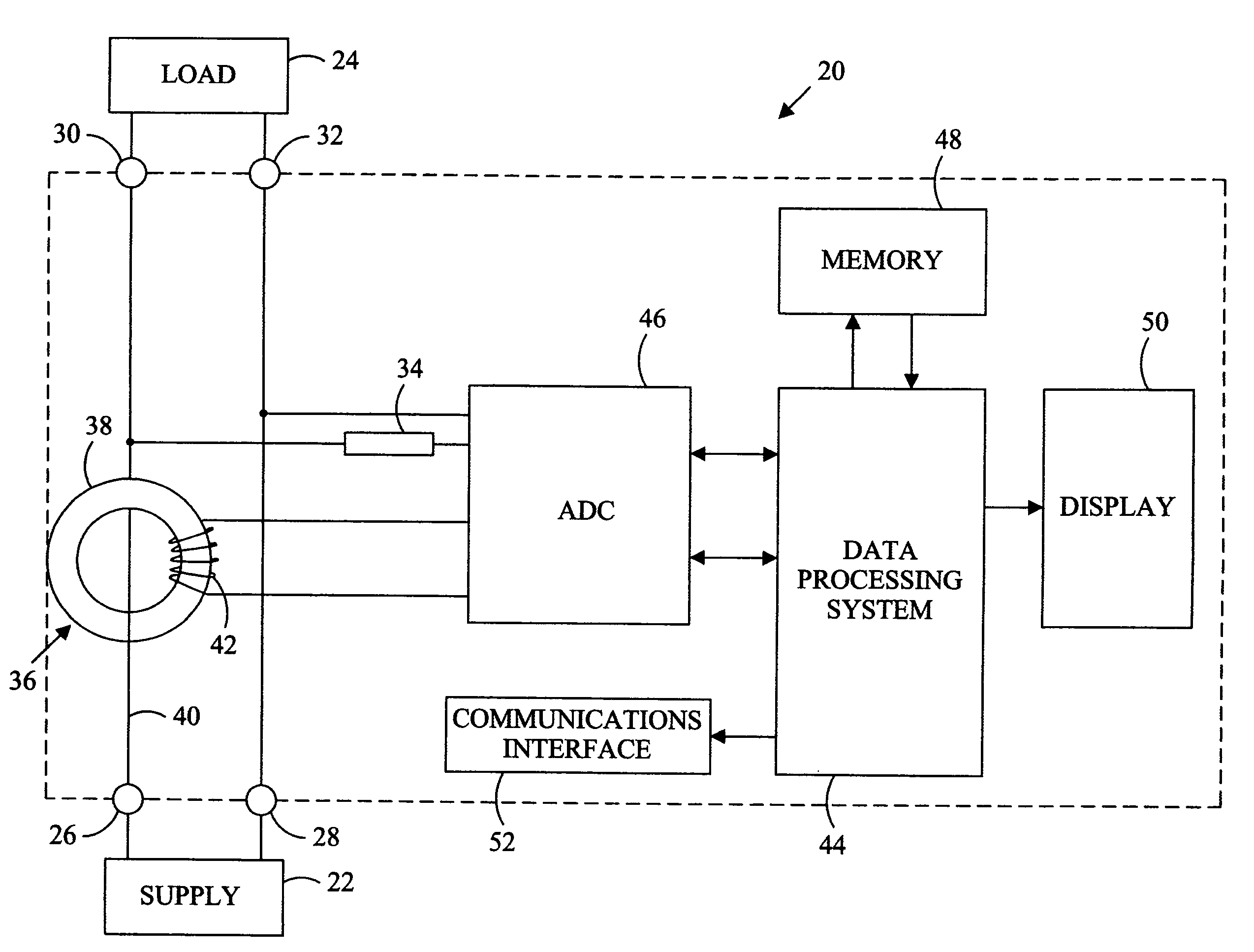
[0023]Referring in detail to the drawings where similar parts of the invention are identified by like reference numerals, and more particularly to FIG. 1, an electrical power meter 20 is adapted for connection between a supply 22 and a load (or loads) 24 of an electrical distribution system via input terminals 26, 28 and output terminals 30, 32. The supply voltage is sensed through a voltage transducer 34, such a voltage divider resistor and the load current is sensed by a current transducer, commonly a current transformer 36. The exemplary current transformer 36 comprises a toroidal core 38 with conductive wire wrapped around the cross-section of the core to form a secondary winding 42. A conductor 40 connecting the supply terminal 26 to the load terminal 30 and passing through the aperture in the center of the toroidal core 38 comprises the primary winding of the current transformer 36. The primary winding has N1 (commonly, N1=1) turns and the secondary winding has N2 turns. Thus,...


PUM

PropertyMeasurementUnit
phase error correction factoraaaaaaaaaa
phase erroraaaaaaaaaa
currentaaaaaaaaaa

Abstract

The data storage and processing resources required for an electric meter are reduced by basing the selection and application of phase error correction on a root mean square load current flowing through the meter.

Description

CROSS-REFERENCE TO RELATED APPLICATIONS[0001]This application claims the benefit of U.S. Provisional Application No. 60 / 613,868, filed Sep. 28, 2004.STATEMENT REGARDING FEDERALLY SPONSORED RESEARCH OR DEVELOPMENT[0002]Not applicable.BACKGROUND OF THE INVENTION[0003]The present invention relates to electric power meters and, more particularly to an electric power meter that incorporates a current transformer.[0004]Monitoring electrical energy usage is a fundamental function within any electric power distribution system and a primary concern of both consumers and providers of electric power. Electrical energy may be monitored for purposes of usage, equipment performance, and power quality. Volts, amps, watts, vars, power factor, harmonics, kilowatt hours, kilovar hours and other power related measurement parameters are commonly monitored. Typically, the voltage and current, measured at a location within the electric power distribution system, are used to determine the electrical param...

Claims


Application Information

Patent Timeline
Patent Type & Authority Patents(United States)
IPC IPC(8): G01R21/06
CPCG01R19/02G01R11/20G01R15/183G01R21/06G01R22/10
Inventor BRUNO, DAVID A.
Owner VERIS INDS
Why Eureka
Try Eureka