Architecture for creating and maintaining virtual filers on a filer

a filer and virtual file technology, applied in the field of server architectures, can solve the problems of granularity of storage, large size of storage system types, and high cost of many applications or “purposes”

Inactive Publication Date: 2008-04-15
NETWORK APPLIANCE INC
View PDF5 Cites 61 Cited by
  • Summary
  • Abstract
  • Description
  • Claims
  • Application Information

AI Technical Summary

Benefits of technology

[0024]The present invention relates to an architecture that provides the ability to create and maintain, with substantial flexibility and fine granularity, multiple instances of virtual servers, such as virtual filers (vfilers), within a server, such as a filer platform. A vfiler is a logical partitioning of network and storage resources of the filer to establish an instance of a multi-protocol server. Each vfiler is maintained and executed independent of other vfilers on the platform. Dedicated filer resources, such as units of storage and network addresses of network interfaces, may be grouped and partitioned to establish security domains within the filer. Yet common filer resources, such as a storage operating system and a file system, may be shared among the vfilers.
[0027]Advantageously, the novel vfiler architecture facilitates both consolidation of virtual servers and their respective data applications on a single filer, as well as encapsulation of all server network and storage resources. Server consolidation is achieved through the creation of vfilers, each of which is associated with a security domain (one for each supported access protocol). The security domains are completely disjoint, thereby providing separate and independent vfilers within the same filer platform. This aspect of the invention is particularly useful in the case of a storage service provider, wherein the data applications of multiple client organizations are hosted on the filer. Each client organization can access only its own vfiler and is entirely unaware that it is sharing the same physical filer with other organizations. The novel architecture thus obviates the need to dedicate a filer for each client organization.

Problems solved by technology

This type of storage system is generally too large and expensive for many applications or “purposes”.
Even a typical minimum storage size of a volume (or file system) is approximately 150 gigabytes (GB), which is still generally too large for most purposes.
However, there is still the granularity of storage issue since, as noted, the typical minimum storage size of a volume is approximately 150 GB.
In addition, the acquisition of many smaller servers may be more costly than the purchase of a single filer.
Furthermore, the cost of maintenance and administration of many smaller servers is typically substantially more than the cost of maintaining and administering a single filer.
Process-based and server bundling-based server consolidation solutions typically do not provide different security characteristics for each of the server instances running on the platform.
This raises the issue as to how the clients of a particular domain refer to their data.
Migration and reconfiguration of data on storage resources of a server is typically not transparent to a client system; in fact, this issue is often resolved by requiring the client system to change its path descriptor to its data.
Such an approach is generally undesirable because it requires action on behalf of the client system.
Moreover, if the storage resources are consolidated on one or more servers, it is possible that those servers may not be in the same security domain as the users accessing those resources.
However, these techniques do have other limitations.
This direct assignment approach restricts resource management flexibility, particularly with respect to “logical” reassignment of resources among the virtual servers.
This also hinders evolutionary growth of the server consolidation implementation because all partitioning and sizing decisions must be made at the time of consolidation and cannot be easily changed later as the consolidated servers evolve.

Method used


Image

  • Architecture for creating and maintaining virtual filers on a filer
  • Architecture for creating and maintaining virtual filers on a filer
  • Architecture for creating and maintaining virtual filers on a filer

Examples


Embodiment Construction

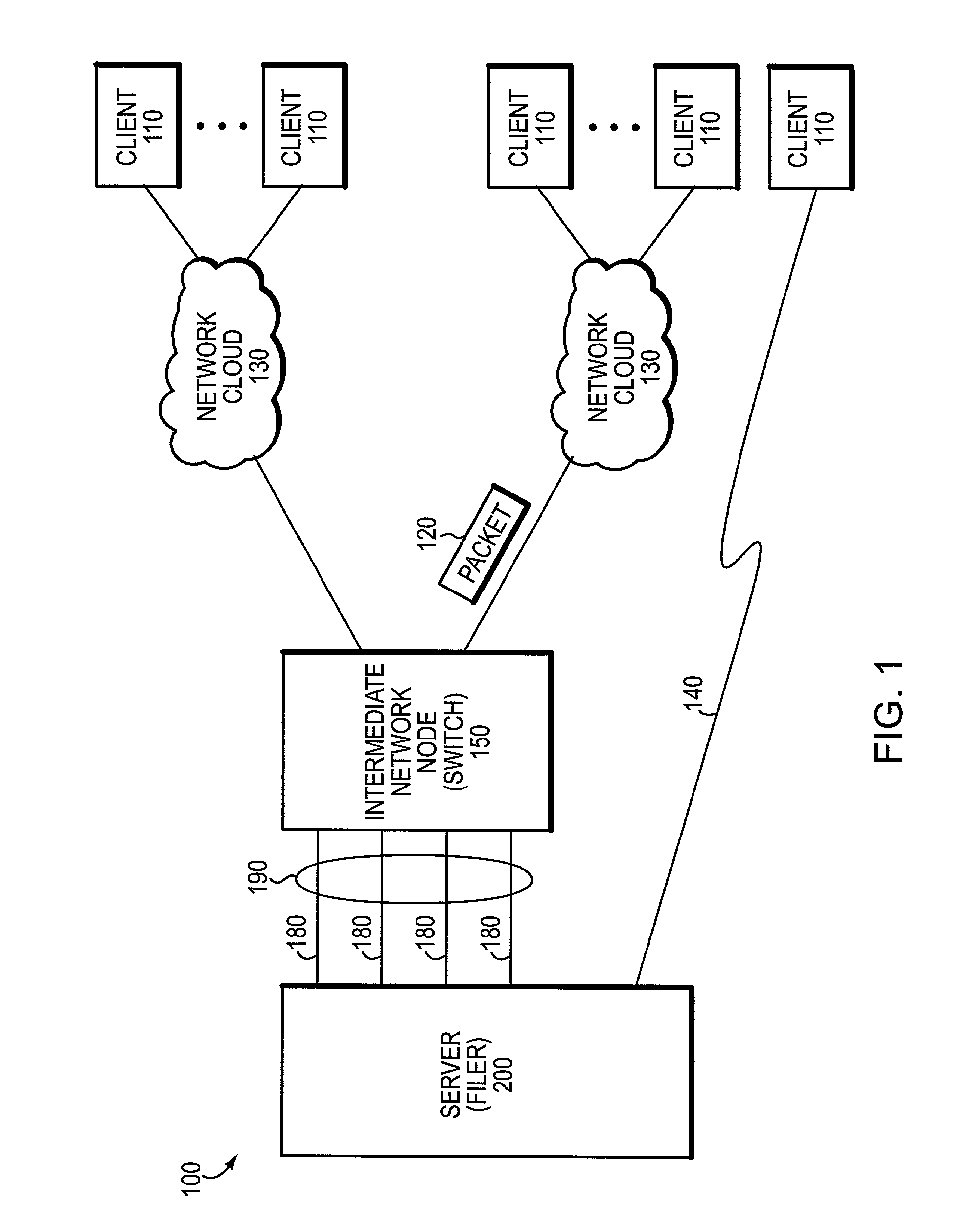
[0038]FIG. 1 is a schematic block diagram of a computer network 100 including a plurality of clients 110 and a file server, such as a network storage appliance, that may be advantageously used with the present invention. The file server or filer 200 is a computer that provides file service relating to the organization of information on storage devices, such as disks. The clients 110 may be general-purpose computers configured to execute applications including file system protocols, such as the conventional Common Internet File System (CIFS) and Network File System (NFS) protocols. Moreover, the clients 110 may interact with the filer 200 in accordance with a client / server model of information delivery. That is, each client may request the services of the filer, and the filer may return the results of the services requested by the client, by exchanging packets 120 encapsulating, e.g., the CIFS and NFS protocol formats over the network 100. It will be understood to those skilled in th...


PUM


Abstract

An architecture provides the ability to create and maintain multiple instances of virtual servers, such as virtual filers (vfilers), within a server, such as a filer. A vfiler is a logical partitioning of network and storage resources of the filer platform to establish an instance of a multi-protocol server. Each vfiler is allocated a subset of dedicated units of storage resources, such as volumes or logical sub-volumes (qtrees), and one or more network address resources. Each vfiler is also allowed shared access to a file system resource of a storage operating system. To ensure controlled access to the allocated and shared resources, each vfiler is further assigned its own security domain for each access protocol. A vfiler boundary check is performed by the file system to verify that a current vfiler is allowed to access certain storage resources for a requested file stored on the filer platform.

Description

FIELD OF THE INVENTION[0001]The present invention relates to server architectures and, more specifically, to an architecture that enables instantiation of multiple logical servers within a single physical server platform.BACKGROUND OF THE INVENTION[0002]A file server is a computer that provides file service relating to the organization of information on writeable persistent storage devices, such memories, tapes or disks. The file server or filer may be embodied as a storage system including a storage operating system that implements a file system to logically organize the information as a hierarchical structure of directories and files on, e.g., the disks. Each “on-disk” file may be implemented as set of data structures, e.g., disk blocks, configured to store information, such as the actual data for the file. A directory, on the other hand, may be implemented as a specially formatted file in which information about other files and directories are stored.[0003]A storage system may be...

Claims


Application Information

Patent Timeline
Patent Type & Authority Patents(United States)
IPC IPC(8): G06F12/14G06F12/00G06F9/46H04L29/06H04L29/08
CPCH04L63/10H04L69/329H04L67/10H04L63/104H04L63/0807
Inventor MUHLESTEIN, MARKBANGA, GAURAV
Owner NETWORK APPLIANCE INC
Why Eureka
Try Eureka