Quick change bend tooling bolster

a tooling bolster and quick change technology, applied in the field of tube bending machines and tooling sets, can solve the problems of increasing so as to achieve the effect of reducing the cost of change-over periods and reducing the inconvenience of changing the bolster

Active Publication Date: 2008-04-22
GM GLOBAL TECH OPERATIONS LLC
View PDF9 Cites 34 Cited by
  • Summary
  • Abstract
  • Description
  • Claims
  • Application Information

AI Technical Summary

Benefits of technology

[0006]Responsive to this need, the present invention provides an assembly of properly positioned and interconnected tube bending components adapted for use with conventional tube bending machines. The assembly enables the concurrent connection and disconnection of the entire assembly to and from the machine, thereby resulting in drastically reduced change-over periods relative to conventional tool bending processes. Among other things, the invention is further useful for facilitating the production of more complex bent tube geometries having multi-compound bends, and for allowing off-line bend tool set-up.

Problems solved by technology

The change-over period results in considerable down-time to the machine, as well as additional labor costs.
In a repetitive environment, such as an assembly-line process, the costs associated with change-over periods present increasingly significant concerns; especially given that a typical change over of a complete tool set may take up to four hours of down-time per machine.
As a result, the percentage of tube bending configurations that can be manufactured on one bender before requiring a complete tooling change has become increasingly limited.
Even with these provisions, however, significant change-over periods and labor costs persist.

Method used


Image

  • Quick change bend tooling bolster
  • Quick change bend tooling bolster
  • Quick change bend tooling bolster

Examples


Embodiment Construction

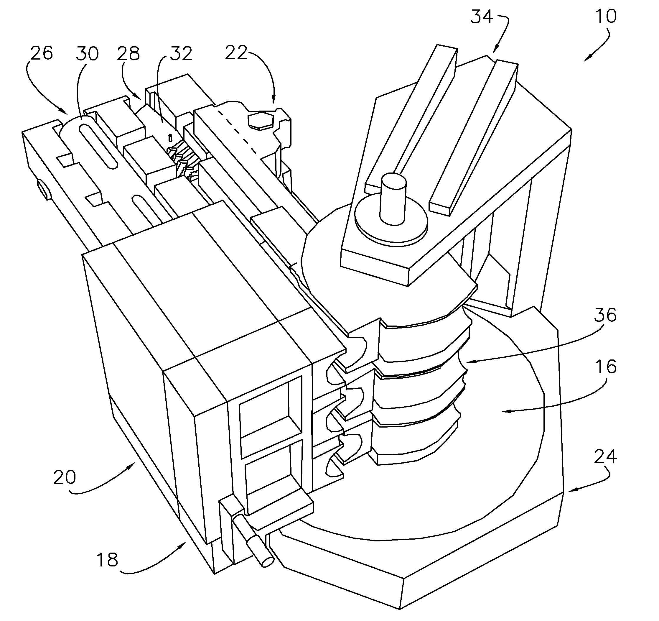
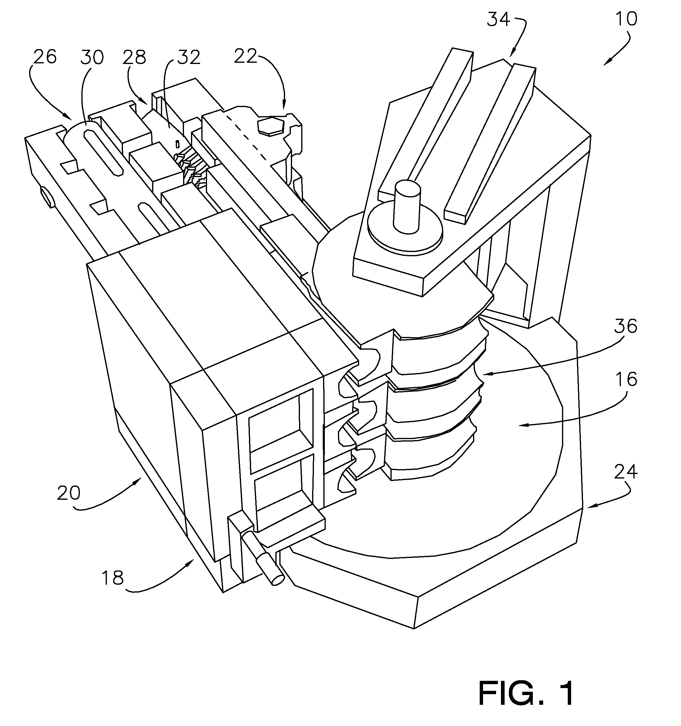
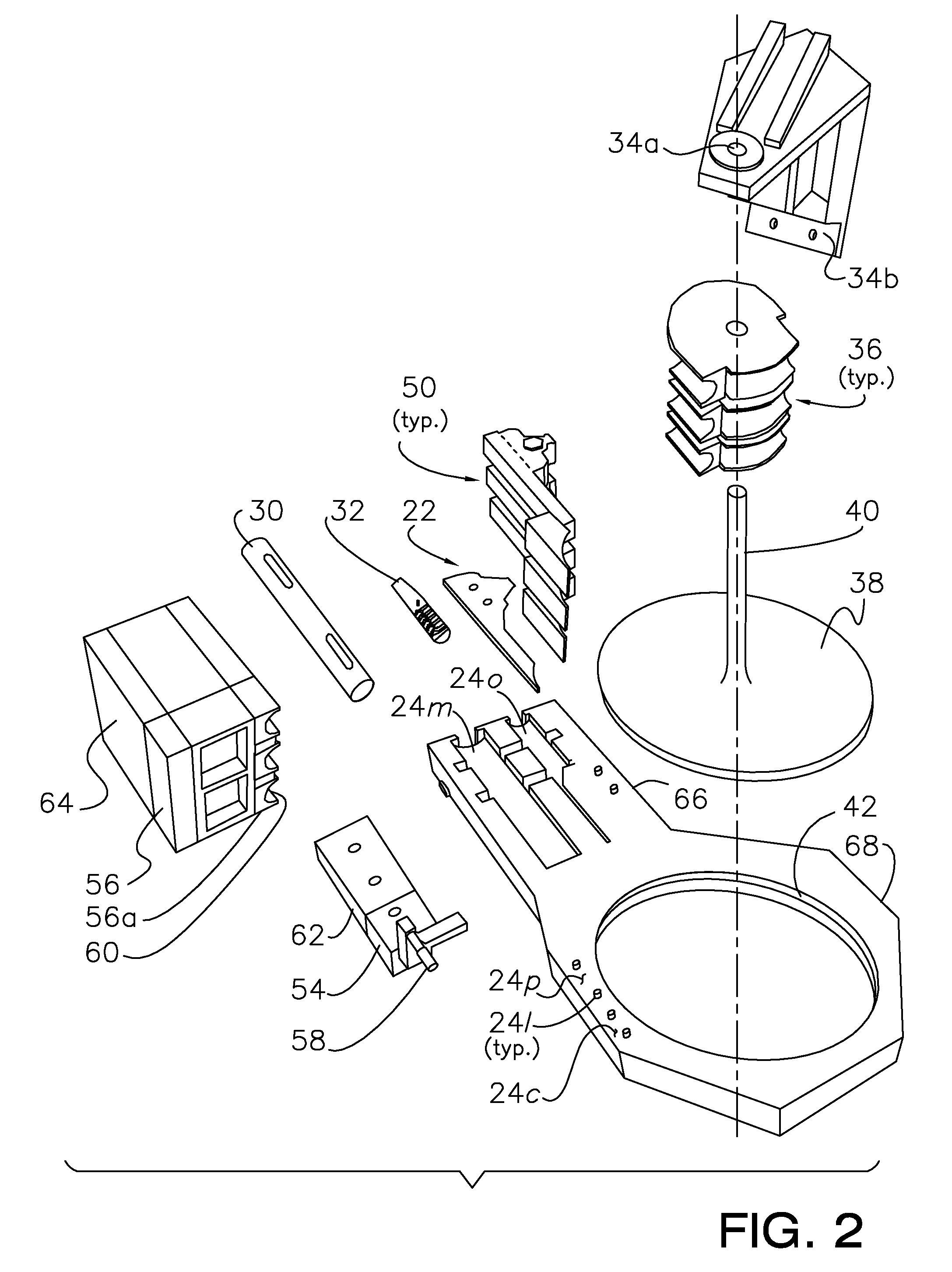
[0027]As shown in FIGS. 1 through 12, the present invention concerns novel tube bending assemblies 10,100 adapted for use with a rotary draw tube bending machine or bender 12 (FIG. 3), such as a computer-numerically-controlled (CNC), numerically-controlled (NC), or conventional type tube bender. As is well known in the art, the rotary draw bender 12 functions to compress a tube 14 against a bending profile, so that the point at which bending takes place is stationary and the profile lies tangential to the incoming line of the tube 14 (compare FIGS. 3 and 3a, and 10 and 10a). Typically, to achieve this end the bender 12 rotates a bend die and utilizes a series of other dies to hold and apply pressure to the tube. The bender 12 may utilize a manual, mechanically assisted manual, electrical, hydraulic, or electro-hydraulic drive system to effect rotational displacement. The preferred assemblies 10,100 are described and illustrated herein, with respect to rotary draw bending; however, i...


PUM

PropertyMeasurementUnit
down-timeaaaaaaaaaa
heightaaaaaaaaaa
holding forceaaaaaaaaaa

Abstract

A tube bending assembly adapted for use with a rotary draw bender, and preferably including a bend die mounting unit for securing a plurality of stacked bend dies drivenly coupled to the bender, a bend die tower unit for structurally supporting the bend die mounting unit, a wiper die mounting unit for securing a wiper die adjacent a selected bend die, a clamp die mounting unit for positioning and securing a clamp die, a pressure die mounting unit for securing a pressure die adjacent the clamp die, a mandrel saddle unit for positioning and enabling the utilization of a mandrel assembly, a collet saddle unit for positioning and enabling the utilization of a collet, and a bolster unit that interconnects the units, so as to present an integrated assembly capable of concurrent disconnection from and connection to the bender, and thereby reducing the tool set change-over period.

Description

FIELD OF THE INVENTION[0001]The present invention relates generally to tube bending machines and tooling sets. More particularly, the invention concerns an assembly configured to facilitate the proper positioning, interconnection, and retention of a complete bend tooling set for quick connection to and disconnection from a tube bending machine.BACKGROUND OF THE INVENTION[0002]Conventional tube-bending machines or benders primarily employ compression, press and rotary draw methods to bend tubes along circular arcs. These machines and methods are commonly utilized in various industrial applications, including automobile and aircraft assembly, and equipment / conduit manufacture. These machines typically include a series of dies and a drive mechanism that cooperate to impart pressure upon a tube, so that the tube bends to a predetermined form. More particularly, with respect to rotary draw bending, a bend die is positioned adjacent the desired section of the tube. The tube is held in pla...

Claims


Application Information

Patent Timeline
Patent Type & Authority Patents(United States)
IPC IPC(8): B21D9/05
CPCB21D7/024
Inventor WOHLENHAUS, DOUGLAS T.MARTINEZ, ARTURO M.LOVELL, MICHAEL H.CLINE, MARK A.FRIDDELL, DAVID R.
Owner GM GLOBAL TECH OPERATIONS LLC
Why Eureka
Try Eureka