Inflator and airbag apparatus

a technology of airbags and airbags, which is applied in the direction of pedestrian/occupant safety arrangements, vehicular safety arrangements, vehicle components, etc., can solve the problems of increasing the assembling reducing difficult to produce the inflator, so as to reduce the manufacturing cost of the inflator, increase the distance between the welded parts, and avoid the effect of welding heat from the chemical

Inactive Publication Date: 2008-04-22
TAKATA CORPORATION
View PDF30 Cites 11 Cited by
  • Summary
  • Abstract
  • Description
  • Claims
  • Application Information

AI Technical Summary

Benefits of technology

[0015]In the inflator in the first aspect, the tank and the gas generator are coupled to each other by the coupling mechanisms provided in both of them. Accordingly, it is not necessary to perform a welding operation to couple both the tank and gas generator to each other. In the second aspect, when the coupling mechanisms use screws or tight-fitting, the coupling becomes extremely easy.
[0016]In the inflator in the third aspect, the nozzle protrudes from the gas generator, and the front end of the nozzle is welded to the tank. Accordingly, it is possible to increase a distance between the welded part and the chemical in the gas generator, thereby keeping welding heat away from the chemical. It is easy to perform the welding operation, and the manufacturing efficiency of the inflator improves.
[0017]In the inflator in the fourth and fifth aspects, the gas generator and the tank previously charged with the gas are coupled to each other. Accordingly, it is possible to combine a tank having a different gas pressure or capacity and a gas generator having a different gas-generating characteristic to obtain various output characteristics. It is not necessary to provide a gas-charging device in an assembling process of the inflator, thereby reducing assembling cost of the inflator.

Problems solved by technology

Accordingly, it is difficult to produce the inflator and reduce manufacturing cost of the inflator.
When the gas is charged after the tank and the gas generator are welded, it is necessary to provide a gas-charging device in an assembling process of the inflator, thereby increasing assembling cost of the inflator.

Method used


Image

  • Inflator and airbag apparatus
  • Inflator and airbag apparatus
  • Inflator and airbag apparatus

Examples


Embodiment Construction

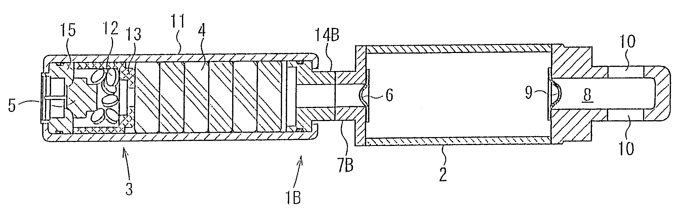
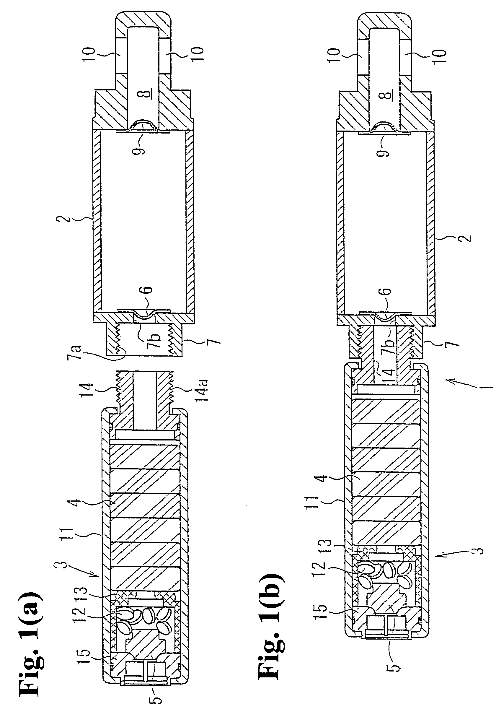
[0021]Hereinafter, embodiments of the present invention will be described with reference to the accompanying drawings. FIGS. 1(a) and 1(b) are sectional views of an inflator according to a first embodiment of the present invention, wherein FIG. 1(a) shows a state before a gas generator and a tank are coupled to each other, and FIG. 1(b) shows a state in which the gas generator and the tank are coupled to each other.

[0022]An inflator 1 comprises a substantially cylindrical tank 2; a gas generator 3 that contains chemicals 4 and an initiator 5 and is fixed to one end of the tank 2; a first sealing plate 6 that separates an interior of the gas generator 3 from a gas inlet 7 at one end of the tank 2; and a second sealing plate 9 that separates the other end of the tank 2 from a guide hole 8 communicating with a gas outlet 10.

[0023]The tank 2 is made of steel and contains a gas such as nitrogen, argon, and helium with a pressure of about 10,000 to 70,000 kPa. A cylindrical gas inlet 7 pr...


PUM


Abstract

An inflator is a hybrid inflator constructed by coupling a tank charged with a pressurized gas and a gas generator containing a gas-generating chemical. A coupling mechanism is provided in each of the tank and the gas generator, and the tank and the gas generator are coupled to each other with the coupling mechanisms.

Description

BACKGROUND OF THE INVENTION AND RELATED ART STATEMENT[0001]The present invention relates to an inflator used in an airbag apparatus, and in particular, to a hybrid inflator for releasing a gas generated from a gas-generating chemical and a pressurized gas stored therein. In addition, the present invention relates to an airbag apparatus using the inflator.[0002]A hybrid inflator includes a gas generator containing gas-generating chemicals ignited by an initiator; and a tank charged with a pressurized gas. When the chemicals start to react by the initiator, the reaction gas flows into the tank. Then, a sealing plate separating the tank and a gas outlet is ruptured, and a mixed gas of a gas stored in the tank (hereinafter referred to as stored gas) and the reaction gas is released from the gas outlet.[0003]Japanese Patent Publication (Kokai) No. 2003-81050 discloses an inflator in which one end of a cylindrical tank is attached to a gas generator by welding, and a gas outlet is provide...

Claims


Application Information

Patent Timeline
Patent Type & Authority Patents(United States)
IPC IPC(8): B60R21/272B60R21/26
CPCB60R21/272
Inventor YANO, KANJINISHIMURA, JUN
Owner TAKATA CORPORATION
Why Eureka
Try Eureka