
Method and arrangement for a termination of an electrical cable

a technology of electrical cables and terminations, which is applied in the direction of electrically conductive connections, basic electric elements, electrical apparatus, etc., can solve the problems of time-consuming, incorrect filling of the insulator body, and complicated to ensure the maintenance of free space, so as to achieve more economical and safer solutions.

Inactive Publication Date: 2008-04-22
PRYSMIAN CAVI E SISTEMI ENERGIA
View PDF24 Cites 9 Cited by
  • Summary
  • Abstract
  • Description
  • Claims
  • Application Information

AI Technical Summary

Benefits of technology

This approach simplifies the installation process, enhances the reliability of the termination by ensuring volume expansion accommodation, and reduces the risk of mechanical damage or electrical breakdown, leading to a more economical and safer solution.

Problems solved by technology

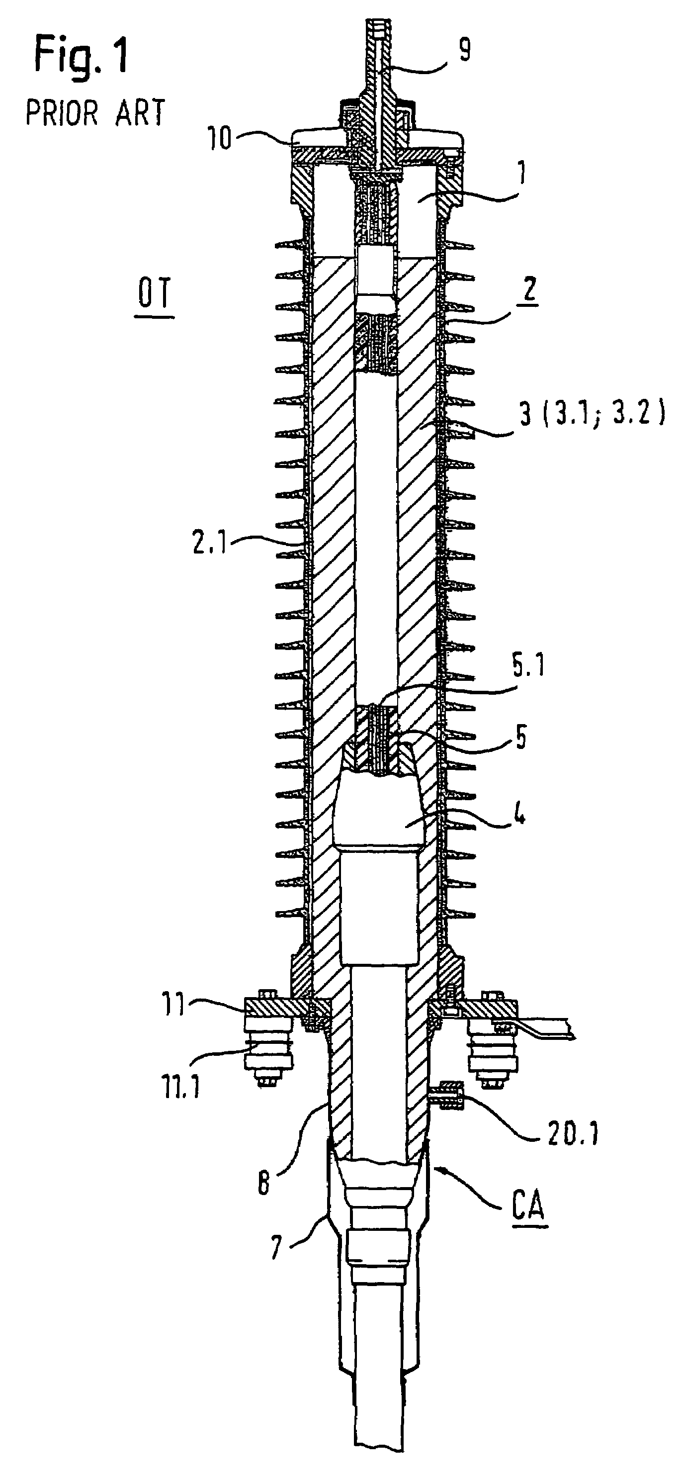
Secondly, it must be considered that the outdoor termination OT is arranged in open space and is thus exposed to all kinds of environmental influences, in particular large changes in temperature and / or large stresses due to snow or wind.
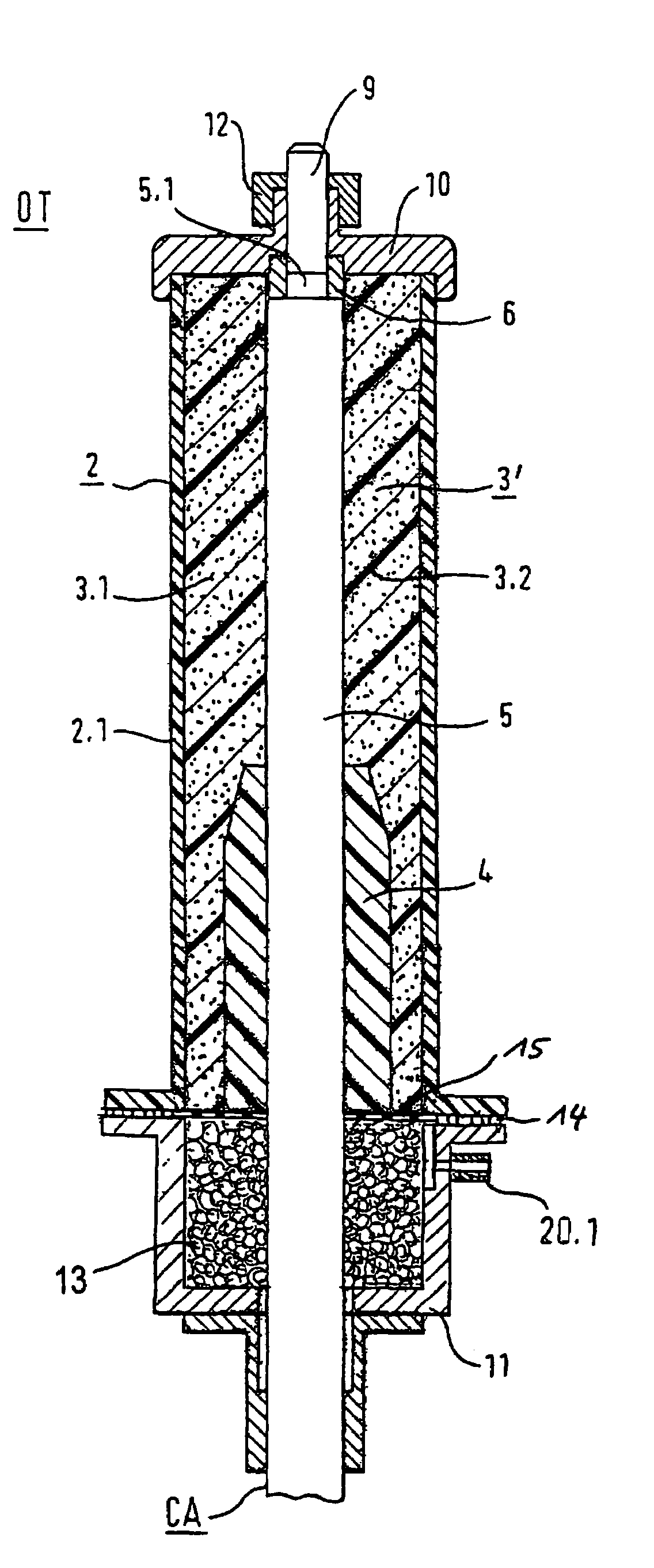
Under such conditions, i.e. by using such known methods of building a termination of a cable end, the applicant perceived that it is quite complicated to ensure that a free space is maintained on top of the termination during the installation, said space being necessary for accommodating volume changes of the insulating material inside the termination.
In case the filling of the insulating material into the termination is carried out by taking into account a filling mark possessed by the insulator body, an appropriate displacement of the air between the solid particles can not be guaranteed above all if the viscosity of the insulating compound is high, therefore an incorrect filling of the insulator body can occur.
Additionally, said filling step is time consuming (it may take about an hour) and is a source of unwanted errors.
Such method is also quite complicated.

Method used


Image

  • Method and arrangement for a termination of an electrical cable
  • Method and arrangement for a termination of an electrical cable
  • Method and arrangement for a termination of an electrical cable

Examples


fourth embodiment

OF A TERMINATION

[0118]FIG. 8 shows a forth embodiment of a termination according to the present invention.

[0119]In particular FIG. 8 shows a volume change compensation member 13 on top of a termination provided with a conical insulator body 2. Said volume change compensation member is in the form of an inflatable body, shown already inflated in FIG. 8

[0120]According to FIG. 8, the volume change compensation member 13 is shown positioned at the top of the termination, while the insulator body 2 is already filled with the insulating material 3 and the upper plate 10 is installed.

[0121]The height of the inflatable body is chosen to occupy the necessary volume at the atmospheric pressure. The pressure within the inflated body, generated for example by a suitable pump is for example of about 0,5 bar and the body increases its volume.

[0122]In this particular embodiment the material of the inflatable body is a semi-conductive rubber and the inflatable body improves the electrical strength ...

first embodiment

OF A METHOD TO BUILD A TERMINATION

[0124]FIG. 9 shows a first embodiment of the method of building a termination of an electrical cable in accordance with the invention.

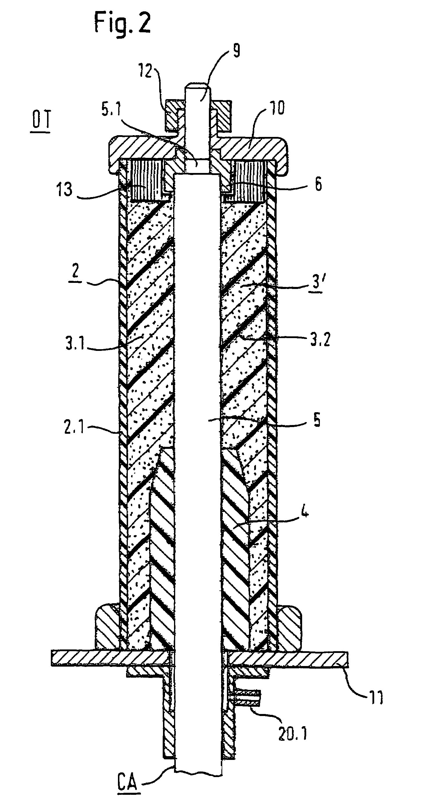
[0125]Particularly FIG. 9 shows a first embodiment of the method of building a first embodiment of the termination as described above with reference to FIG. 2. However, this first embodiment of the method of building a termination is also applicable to the modification of the second embodiment of a termination as described above with reference to FIG. 3, in which the volume change compensation member 13 in the form of a foam body is taken out from the termination when the step of filling the insulating compound is completed.

[0126]The procedure starts at step S1, in which an insulator body 2, with the parts as shown in FIG. 1 and FIG. 2 necessary for the electrical functioning of the outdoor termination, is prepared and a high voltage cable CA is provided inside said insulator body 2.

[0127]In a second step S2, solid pa...

second embodiment

OF A METHOD TO BUILD A TERMINATION

[0132]FIG. 10 shows a second embodiment of the method of building a termination of an electrical cable in accordance with the invention.

[0133]Particularly FIG. 10 shows a second embodiment of the method of building a termination as described with reference to FIG. 3 and 8. The particular features of said embodiments are that the volume change compensation member 13 is located in the upper area of the termination near the connector stalk and that the volume change compensation member 13 remains in the termination for normal use.

[0134]The procedure starts at step S11, which is identical to step S1 of the procedure shown in FIG. 9.

[0135]In a second step S21, solid particles 3.1 are filled into the insulator body 2 from the upper portion of the termination. For example a filling of about 90% of the interior of the insulator body 2 is carried out and a predetermined space is left free at the upper portion of the insulator body 2. In case the insulating m...


PUM


Abstract

A method of building a cable termination is provided. The termination has an outer insulator body, a substantially longitudinally extended interior member having the electrical cable to be terminated, having a conductor for carrying load, an insulating material filled in a cavity between the outer insulator body and the interior member and means for accommodating volume expansions of the insulating material filled within the cavity. The cavity is created by introducing the interior member into the insulator body, filling the insulating material into the cavity and sealing the termination. A volume change compensation member having a predetermined volume to accommodate volume expansions of the insulating material within the cavity is placed into the cavity. Respective terminations are also provided.

Description

CROSS REFERENCE TO RELATED APPLICATION[0001]This application is a national phase application based on PCT / EP2002 / 007077, filed Jun. 26, 2002, the content of which is incorporated herein by reference.FIELD OF THE INVENTION[0002]The present invention relates to a method of building a termination of an electrical cable. In particular, the present invention relates to a method of building a termination of an electrical cable said termination comprising an outer insulator body, a substantially longitudinally extended interior member comprising the electrical cable to be terminated, the cable comprising a conductor for carrying load, an insulating material, filled in a cavity between the outer insulator body and the interior member, and means for accommodating volume expansions of the insulating material filled within the cavity, wherein the method comprising the steps of creating the cavity by introducing the interior member into the insulator body; filling in the insulating material int...

Claims


Application Information

Patent Timeline
Patent Type & Authority Patents(United States)
IPC IPC(8): H02G15/02H01R9/05H02G15/00H02G15/06H02G15/068H02G15/22
CPCH02G15/003H02G15/06H02G15/068H02G15/22
Inventor GOEHLICH, LOTHAR
Owner PRYSMIAN CAVI E SISTEMI ENERGIA
Learn More