Ironcore linear brushless DC motor with reduced detent force

a brushless dc motor and linear technology, applied in the direction of dynamo-electric machines, electrical apparatus, magnetic circuit shapes/forms/construction, etc., can solve the problems of limiting the size of wires and the difficulty of machine winding process, and achieve the effect of reducing detent for

Inactive Publication Date: 2008-04-22
BEI SENSORS & SYST
View PDF34 Cites 6 Cited by
  • Summary
  • Abstract
  • Description
  • Claims
  • Application Information

AI Technical Summary

Benefits of technology

[0010]The above and other desirable features are provided by the present invention of a stack structure, and a linear brushless DC motor that incorporates such ...

Problems solved by technology

However, a small slot opening limits the size of the wire that can be used for the winding.
I...

Method used


Image

  • Ironcore linear brushless DC motor with reduced detent force
  • Ironcore linear brushless DC motor with reduced detent force
  • Ironcore linear brushless DC motor with reduced detent force

Examples


Embodiment Construction

[0026]Reference is made to U.S. patent application Ser. No. 10 / 116,495, filed Apr. 3, 2002, and assigned to the assignee of the present disclosure, and which is incorporated herein by reference.

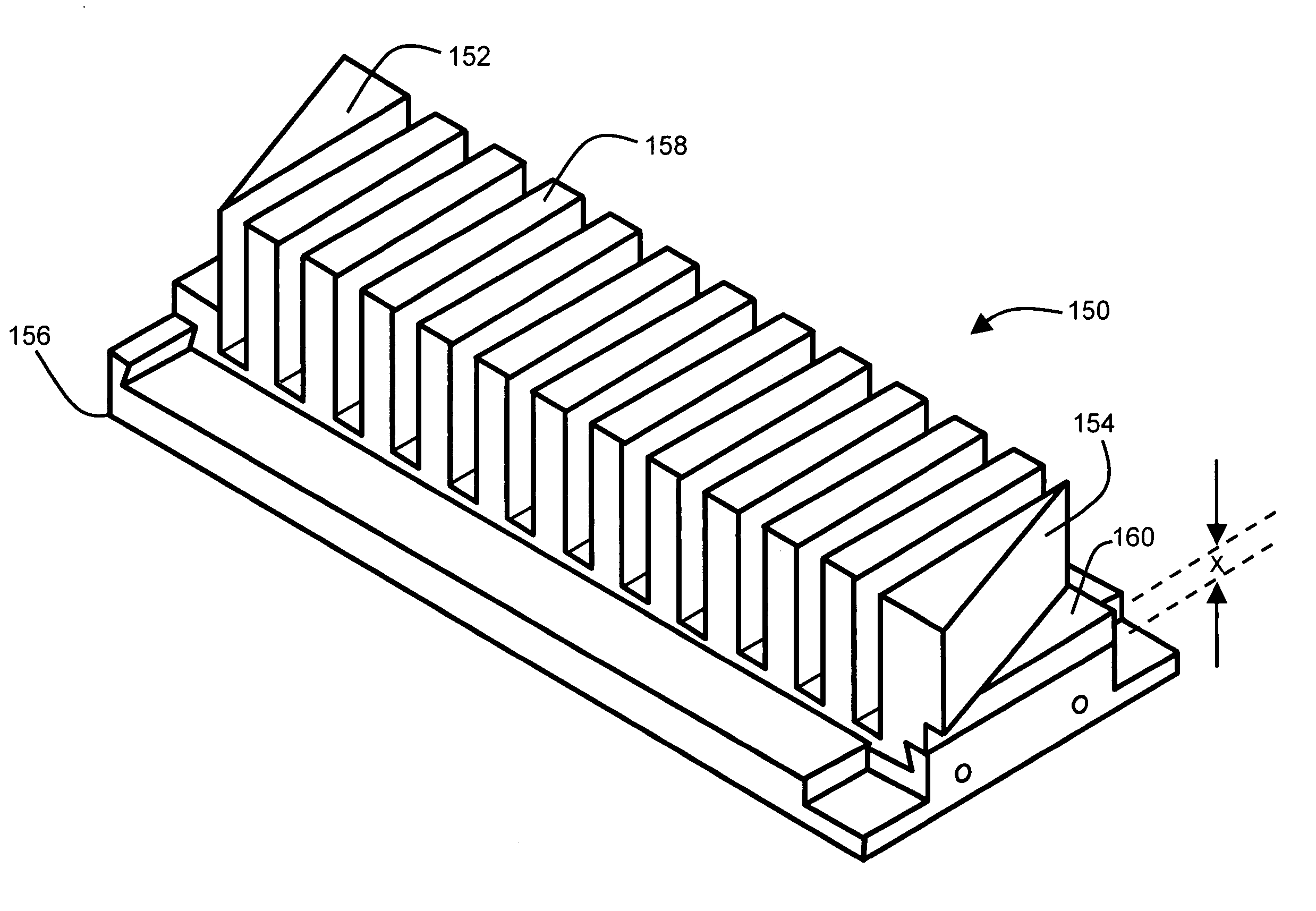
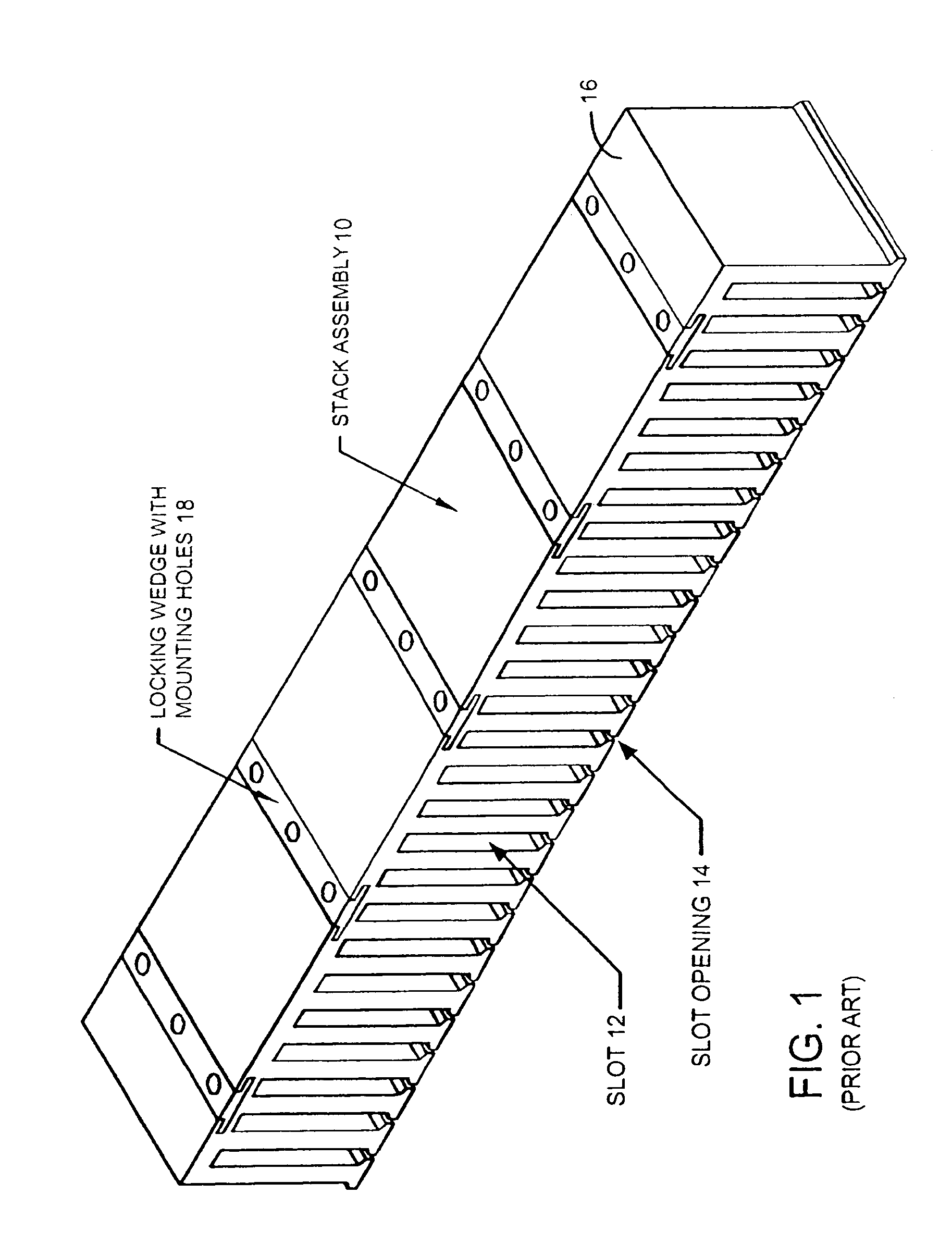
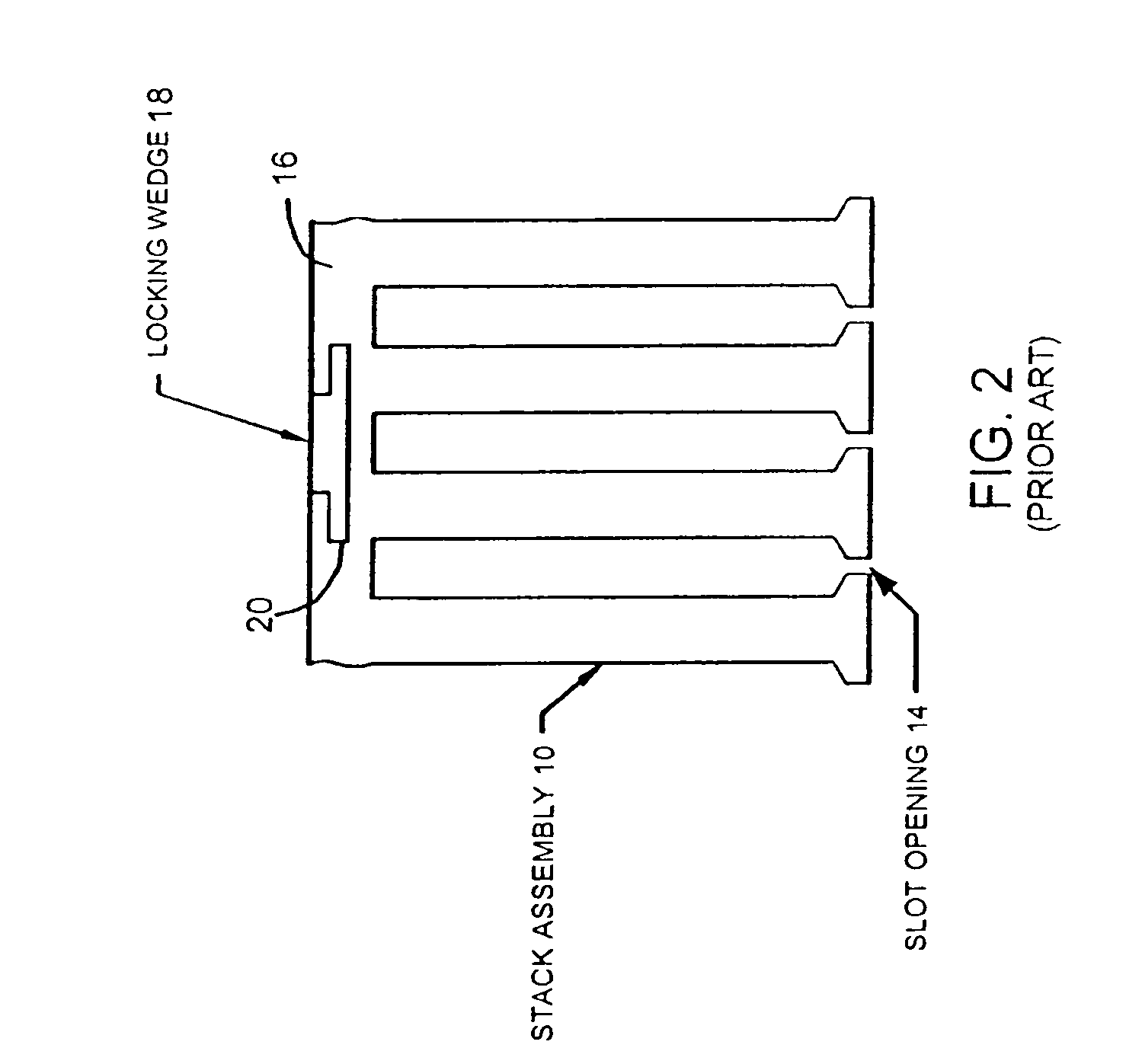
[0027]Referring now to FIG. 3, a portion of the stack assembly 100 of a configuration, which facilitates winding of coils while reducing cogging forces, is illustrated. As can be seen from the figure, the teeth 102 of the stack extend outwardly from base portion 106. The width of the slots 104 separating teeth 102 is substantially the same from bottom (at the base portion 106) to top portion 108 (free ends of the teeth). This is in contrast to tooth designs of previous stack assemblies, for example in FIG. 2, in which the top end of the teeth flares outwardly to narrow the slot opening 14 between teeth.

[0028]According to this embodiment, the top portion 108 of each tooth 102 has two additional notches 110, as can be seen in FIG. 3, to accommodate magnetic wedges 112, as illustrated in FIG. 4....


PUM


Abstract

A linear brushless DC motor is disclosed which provides reduced detent force by way of a stack that features end teeth that are formed to be wedge shaped, and which has a length in the direction of motion which is approximately equal to (Np+½) × pole pitch, where Np equals the number of poles covered by the armature of the brushless DC motor, and the pole pitch equals a distance between centers of two adjacent magnets of opposite polarity in a field assembly of the linear brushless DC motor.

Description

RELATED APPLICATIONS[0001]The present application claims priority under 35 U.S.C. §119(e) from provisional application No. 60 / 476,741, filed Jun. 6, 2003.[0002]This is a continuation-in-part of U.S. patent application Ser. No. 10 / 116,495, filed Apr. 3, 2002 now U.S. Pat. No. 6,919,660, and assigned to the assignee of the present application, which claims the benefit of provisional application No. 60 / 282,546, filed Apr. 9, 2001.TECHNICAL FIELD[0003]The present disclosure is directed generally to linear brushless DC motors, and in particular to an ironcore linear brushless DC motor with reduced detent force.BACKGROUND ART[0004]A typical linear brushless motor of a rectangular configuration consists essentially of two parts: an armature assembly and a field assembly separated from each other by a small air gap.[0005]An armature assembly, in turn, consists of a stack 10 of laminations with a three-phase winding positioned in its slots 12. Such a stack 10 is shown in FIG. 1. A field asse...

Claims


Application Information

Patent Timeline
IPC IPC(8): H02K41/035H02K41/02H02K1/18H02K3/493H02K41/03
CPCH02K1/18H02K3/493H02K41/03
Inventor GODKIN, MIKHAIL
Owner BEI SENSORS & SYST
Why Eureka
Try Eureka