
Image-forming controller, method therefor, program, and storage medium

a controller and image forming technology, applied in the direction of digital output to print units, visual presentation using printers, instruments, etc., can solve the problems of time delay and difficulty in providing a machine that incorporates a plurality of image forming sections at low cos

Inactive Publication Date: 2008-04-22
CANON KK
View PDF10 Cites 10 Cited by
  • Summary
  • Abstract
  • Description
  • Claims
  • Application Information

AI Technical Summary

Benefits of technology

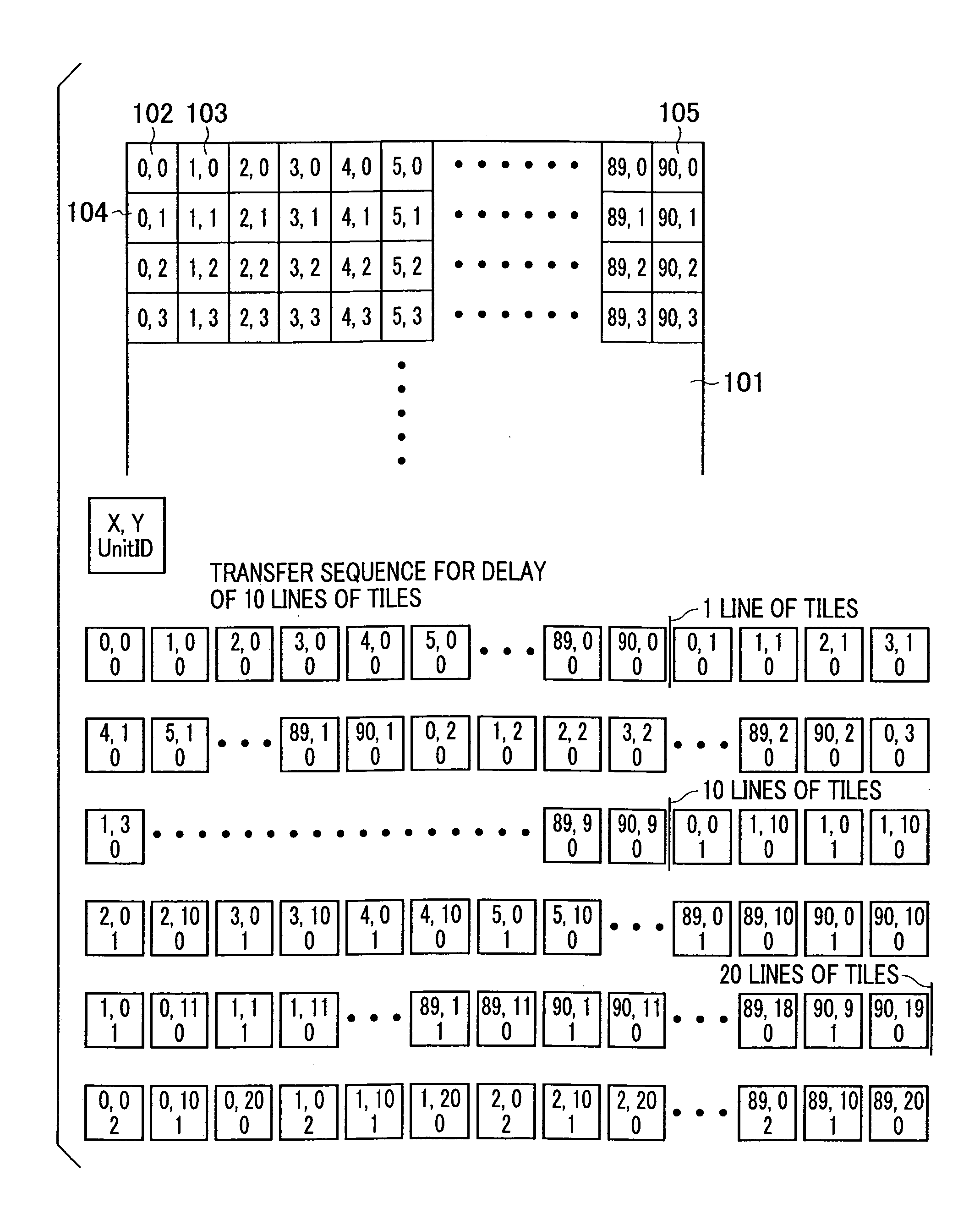
[0011]The present invention has been made to overcome the foregoing problem, and an object of the present invention is to provide an image-forming controller, a method therefor, a program, and a storage medium, which are used for a printer engine having a plurality of image forming sections, without the use of an expensive inter-drum delay memory that has been conventionally used. This is achieved by a configuration in which image data containing an identical tile image stored in a memory in a divided tile pattern is read predetermined multiple times with a delay corresponding to the number of pieces of data corresponding to a delay (lines of tiles) of image formation between image forming sections and is sequentially transferred to rectangle-raster converting means. This allows tile data to be transferred to image output interfaces multiple times in synchronization with data-request timings for corresponding photosensitive drums of a printer engine having image forming sections.
[0013]According to the present invention, it is possible to provide an inexpensive controller that eliminates the need for an expensive inter-drum delay memory, which has been conventionally used for printing an RGB image, thus offering advantages in that a multifunction machine, a printer, and the like having a plurality of drums can be provided at low cost.

Problems solved by technology

However, when the controller for a multifunction machine in the above conventional example is connected to a printer engine that has a plurality of image forming sections and a plurality of photoreceptors for respective colors and that prints each page using the photoreceptors simultaneously at a high speed, time delay occurs after, for example, an RGB image is converted into a YMCK image, because timing of outputting image data in synchronization with the timing of a sheet of paper passing by photosensitive drums, arranged in parallel, varies for each color.
As a result, there is difficulty in providing a machine that incorporates a printer engine having a plurality of image forming sections at low cost.

Method used


Image

  • Image-forming controller, method therefor, program, and storage medium
  • Image-forming controller, method therefor, program, and storage medium
  • Image-forming controller, method therefor, program, and storage medium

Examples


Embodiment Construction

[0037]The present invention is directed to a controller for a multifunction machine that has a CPU, memory, computer connection interface, network interface, printer interface, scanner interface, PDL rendering means, various-still-image processing means, and the like, and that performs scanning, printing, network transferring of image data, rendering of PDL (page description language) data (compiling of PDL data), storing of images, and the like. The configuration and operation of a multifunctional image processing apparatus of the present invention will be described below in detail.

Hardware

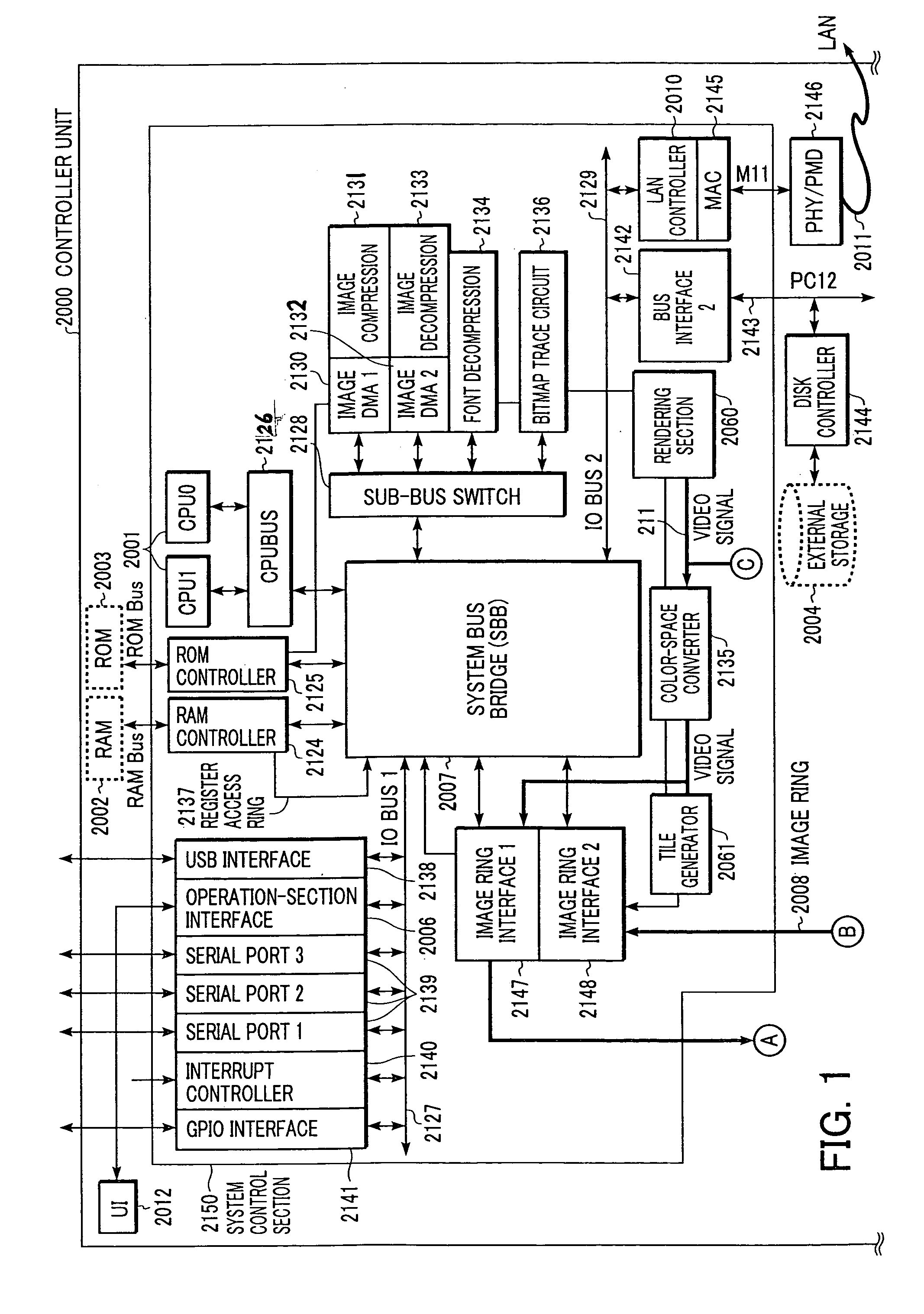
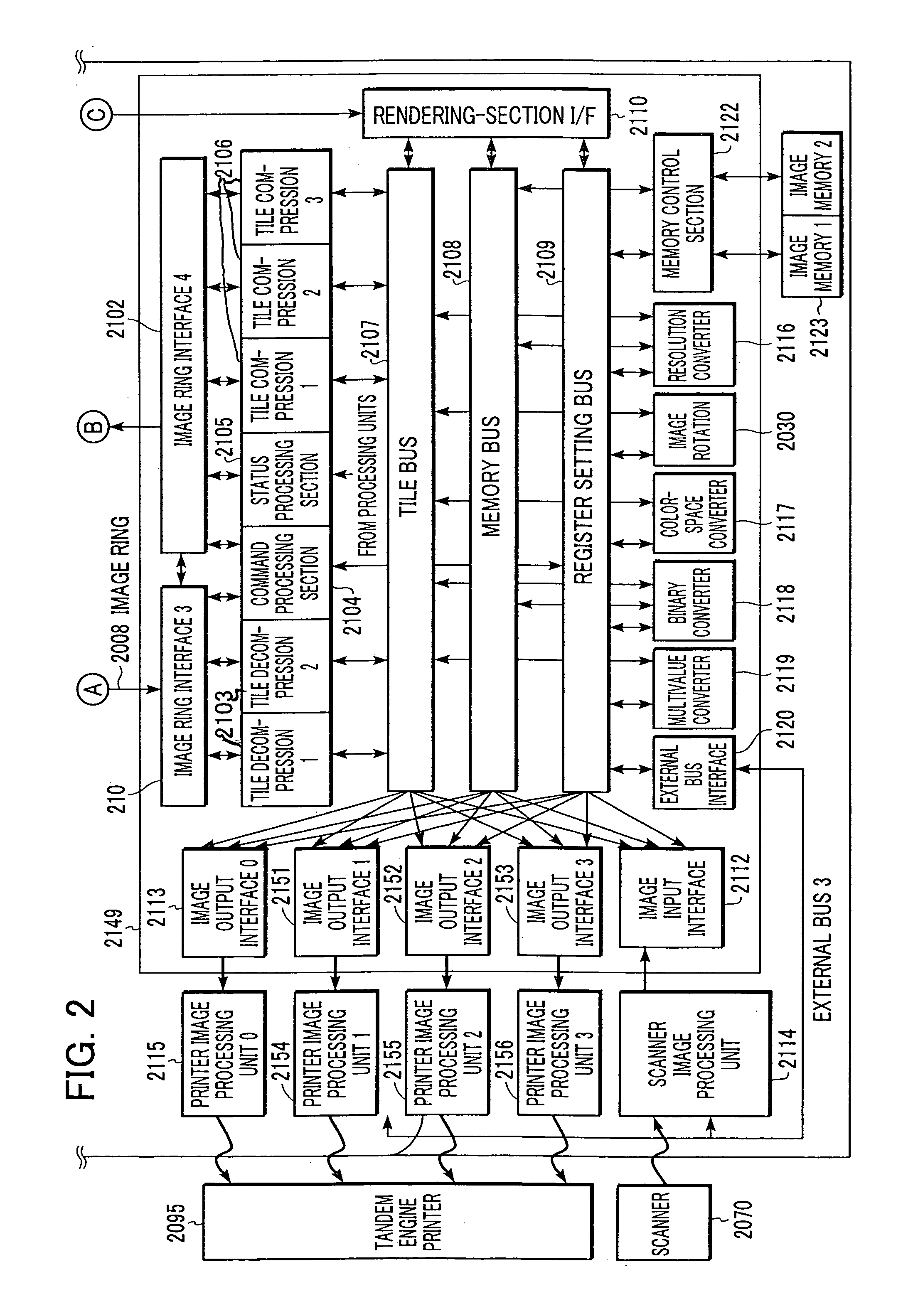
[0038]First, the overall configuration of hardware will be described with reference to FIGS. 1 and 2.

[0039]FIGS. 1 and 2 are block diagrams showing the configuration of a multifunctional image processing apparatus according to an embodiment of the present invention.

[0040]Referring to the figures, a system controller unit 2000 is connected to a scanner 2070, which is an image input apparatus, and ...


PUM


Abstract

A controller for a four-drum printer eliminates a need for an expensive inter-drum delay memory, which has been conventionally used, to print an RGB image and allows a multifunction machine, printer, and the like to be provided at low cost. An image ring interface reads an image data containing the same tile, which is stored in a tile pattern in a RAM, four times with a delay corresponding to a delay (10 lines of tiles) of image formation between image forming sections, and sequentially transfers the image data to four image output interfaces.

Description

BACKGROUND OF THE INVENTION[0001]1. Field of the Invention[0002]The present invention relates to an image-forming controller, a method therefor, a program, and a storage medium.[0003]2. Description of the Related Art[0004]Conventionally, a controller for a multifunctional image processing apparatus (multifunction machine) has been proposed and has a configuration in which raster images after being scanned or rendered are converted into rectangular images, which are then stored, so that the rectangular images can be transferred to rectangle-raster converting means and can be output to a printer as needed.[0005]FIG. 13 is a schematic diagram showing one example of a rectangular-image transfer sequence of a controller for a conventional multifunctional image processing apparatus.[0006]As shown in FIG. 13, in the conventional approach, a page is divided into a plurality of rectangular images (tiles), and a set of an X-coordinate number and a Y-coordinate number is attached to each recta...

Claims


Application Information

Patent Timeline
IPC IPC(8): H04N1/40G06K15/00B41J5/30G06F3/12G06K15/12G06T1/00H04N1/29H04N1/46H04N1/50H04N1/60
CPCG06K15/129H04N1/506
Inventor DATE, ATSUSHI
Owner CANON KK
Learn More