End-user systems for communication services over peer-to-peer internet protocol connections between service providers

Active Publication Date: 2008-04-22
T MOBILE INNOVATIONS LLC
View PDF36 Cites 39 Cited by
  • Summary
  • Abstract
  • Description
  • Claims
  • Application Information

AI Technical Summary

Benefits of technology

[0022]The invention helps solve the above problems with technology that allows an end-user who is connected to a first service provider to obtain packet-based telephony services from a second service provider, even though the end-user is not directly connected to the second service provider. To access the packet-based telephony services of the second service provider, the end-user system uses an IP tunnel through both the first service provider and a peer-to-peer IP connection between the first and second service providers. Advantageously, the end-user may choose packet-based services from many service providers with peer-to-peer IP connections to the first service provider. This dramatically expands end-user choice and stimulates meaningful competition at the service level. The technology offers numerous other advantages.
[0023]The second service provider may implement the technology with few or no changes to their packet telephony network, so the system may be quickly and cheaply deployed. For a service provider with many existing peer-to-peer IP connections, the technology greatly expands potential service coverage areas—even to end-users in remote areas. The end-user obtains true QoS on packet-based telephony, and they may obtain many of the features that currently enjoy with conventional telephone services, such as voice mail and call forwarding. Because the technology restricts or eliminates use of the Internet, issues like communication delay and security are dramatically improved. The invention includes end-user communication devices, methods of operating end-user communication devices, and software products for the user communication devices. Some examples of the invention include end-user communication devices that comprise a telephony interface, network interface, and control circuitry. The telephony interface exchanges telephony signals with a telephone connection to a telephone. The network interface exchanges Internet Protocol (IP) packets with an IP interface for an IP connection to a first service provider. The control circuitry interworks between the telephony signals and the IP packets. For a set of the IP packets being transferred to the IP interface, the control circuitry places a first IP address in the first set of the IP packets for use by the first service provider to route the first set of IP packets over a peer-to-peer IP connection to a second service provider and places packet telephony network addresses in the first set of the IP packets for use by a packet telephony network in the second service provider to provide telephony service.

Problems solved by technology

The above networking arrangement creates a serious problem for end-users.
Exorbitant costs prevent other service providers from deploying their own end-user connections in competition with existing service providers.
The deregulation that was supposed to usher in local competition has yet to deliver a meaningful level of competition in some areas.
Most service providers do not offer any packet-based telephony services that have a legitimate Quality of Service (QoS).
End-users in remote areas may not even have all of these choices.
Unfortunately, computer telephony requires a computer as opposed to a telephone.
The Internet offers only best effort delivery without any guaranteed QoS.
The Internet may require 15 hops to reach a destination adding unacceptable delay to voice communications.
The Internet offers little security and allows hackers to listen to unsophisticated users.
Computer telephony over the Internet does not offer the robust features that some end-users desire, such as voice mail, operator assistance, and call forwarding.

Method used


Image

  • End-user systems for communication services over peer-to-peer internet protocol connections between service providers
  • End-user systems for communication services over peer-to-peer internet protocol connections between service providers
  • End-user systems for communication services over peer-to-peer internet protocol connections between service providers

Examples


Embodiment Construction

[0044]FIGS. 4-9 and the following description depict specific examples to teach those skilled in the art how to make and use the best mode of the invention. For the purpose of teaching inventive principles, some conventional aspects have been simplified or omitted. Those skilled in the art will appreciate variations from these examples that fall within the scope of the invention. Those skilled in the art will appreciate that the features described below can be combined in various ways to form multiple variations of the invention. As a result, the invention is not limited to the specific examples described below, but only by the claims and their equivalents.

Communication Service Provider Environment—FIGS. 4-6

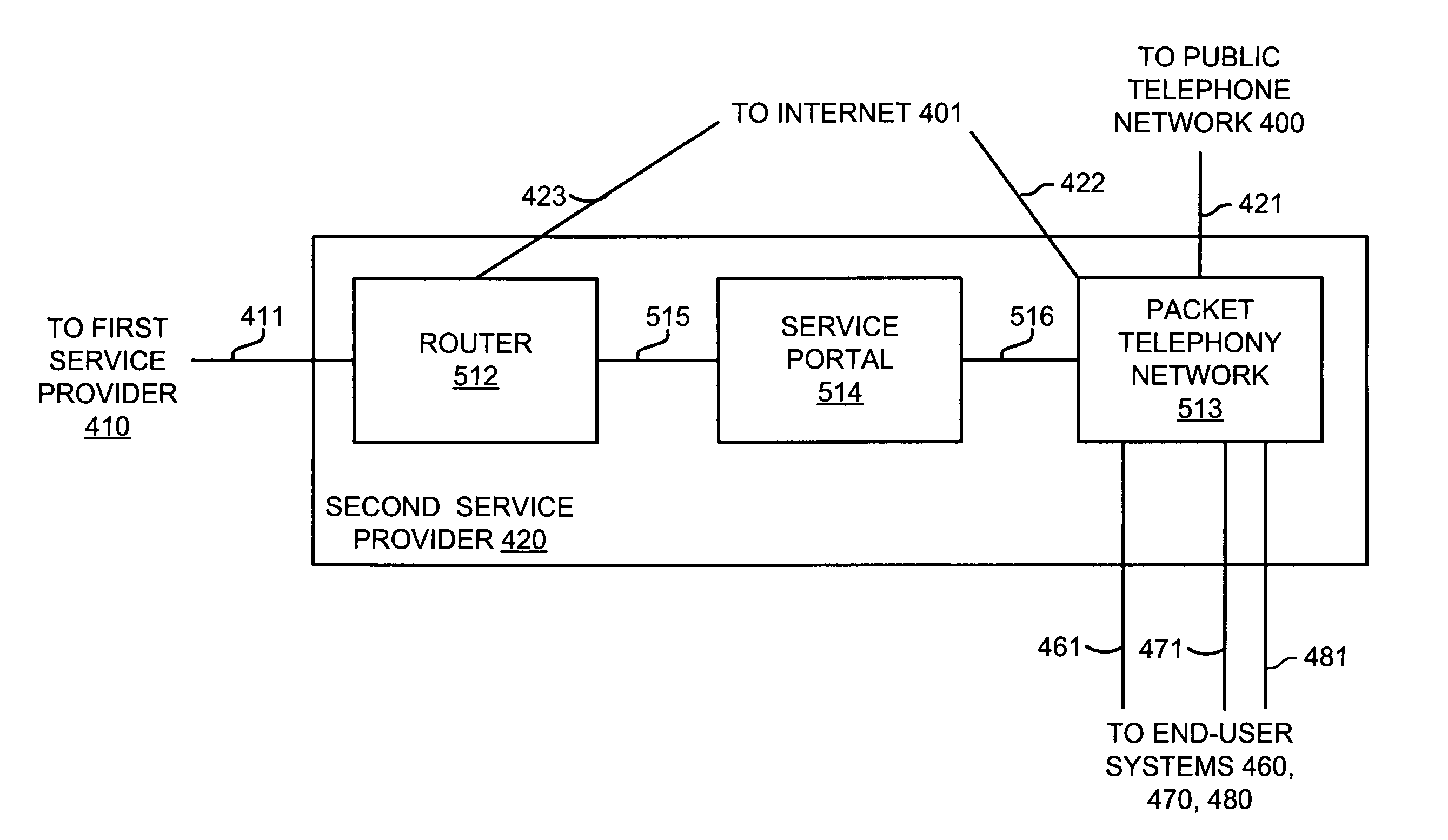
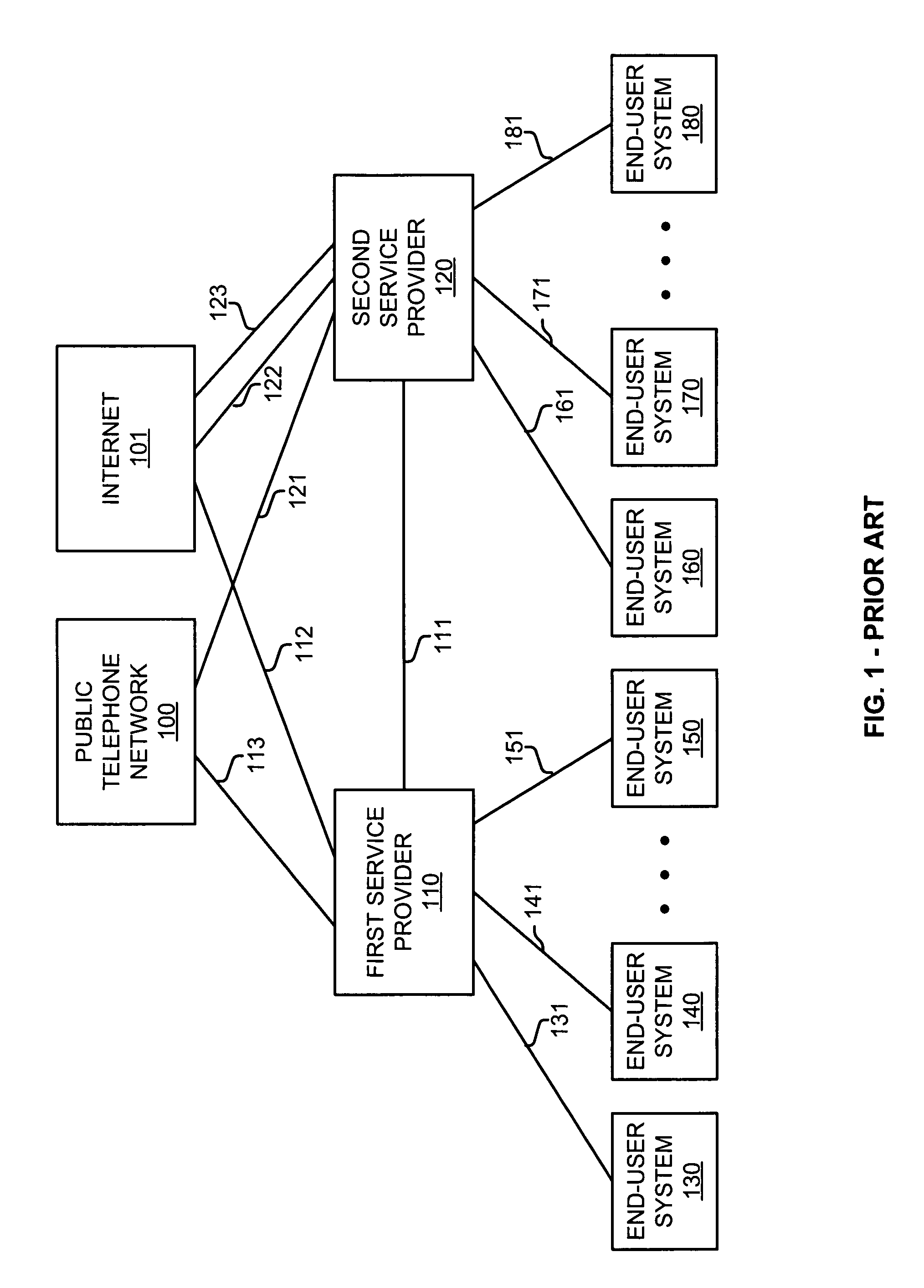
[0045]FIG. 4 illustrates a service provider environment in the prior art. End-user systems 430, 440, 450 are coupled to first service provider 410 over respective connections 431, 441, 451. End-user systems 460, 470, 480 are coupled to second service provider 420 over respective ...


PUM


Abstract

An end-user communication device comprises a telephony interface, network interface, and control circuitry. The telephony interface exchanges telephony signals with a telephone connection to a telephone. The network interface exchanges Internet Protocol (IP) packets with an IP interface for an IP connection to a first service provider. The control circuitry interworks between the telephony signals and the IP packets. For a set of the IP packets being transferred to the IP interface, the control circuitry places a first IP address in the first set of the IP packets for use by the first service provider to route the first set of IP packets over a peer-to-peer IP connection to a second service provider and places packet telephony network addresses in the first set of the IP packets for use by a packet telephony network in the second service provider to provide telephony service.

Description

RELATED APPLICATIONS[0001]Not applicableFEDERALLY SPONSORED RESEARCH OR DEVELOPMENT[0002]Not applicableMICROFICHE APPENDIX[0003]Not applicableBACKGROUND OF THE INVENTION[0004]1. Field of the Invention[0005]The invention is related to the field of communications, and in particular, to end-user systems that use peer-to-peer IP connections to reach packet telephony networks.[0006]2. Description of the Prior ArtCommunication Service Provider Environment in the Prior Art[0007]FIG. 1 illustrates a service provider environment in the prior art. End-user systems 130, 140, 150 are coupled to first service provider 110 over respective connections 131, 141, 151. End-user systems 160, 170, 180 are coupled to second service provider 120 over respective connections 161, 171, 181. First service provider 110 is coupled to public telephone network 100 and Internet 101 by respective connections 112 and 113. Second service provider 120 is coupled to public telephone network 100 and Internet 101 by res...

Claims


Application Information

Patent Timeline
IPC IPC(8): H04L12/66
CPCH04L12/66
Inventor COPE, WARREN B.JOHNSON, HAROLD W.PARKER, BENJAMIN J.
Owner T MOBILE INNOVATIONS LLC
Why Eureka
Try Eureka