Optical harness assembly and method

a technology of optical harnesses and assemblies, applied in the field of optical harnesses and methods, can solve the problems of inconvenient replacement, inflexible, heavy, etc., and achieve the effect of reducing the number of parts

Active Publication Date: 2008-04-22
ZEPHYR PHOTONICS
View PDF12 Cites 51 Cited by
  • Summary
  • Abstract
  • Description
  • Claims
  • Application Information

AI Technical Summary

Benefits of technology

[0011]In accordance with another embodiment of the present invention, there is provided a method of retrofitting an optical harness assembly, as described herein, into a legacy platform. The optical harness assembly includes at least one cable harness having a termination end; at least one electrical connector having connector pins for transporting electrical signals; and at least one active connector conversion unit coupled between the termination end of the cable harness and the electrical connector, the method including: removing a legacy wiring harness; installing the optical harness assembly; and testing the compatibility of the connector pins of the electrical connector with the active connector conversion unit so that the terminal equipment and the harness circuitry can remain the same.

Problems solved by technology

They are relatively heavy, bulky and inflexible.
Wiring harnesses also contribute to undesirable radio frequency interference (“RFI”) and other electromagnetic interference (“EMI”) effects.
Furthermore, it is undesirable to remove, replace or redesign onboard terminal equipment (e.g., LRUs) as a result of the replacement of a wiring harness.

Method used


Image

  • Optical harness assembly and method
  • Optical harness assembly and method
  • Optical harness assembly and method

Examples


Embodiment Construction

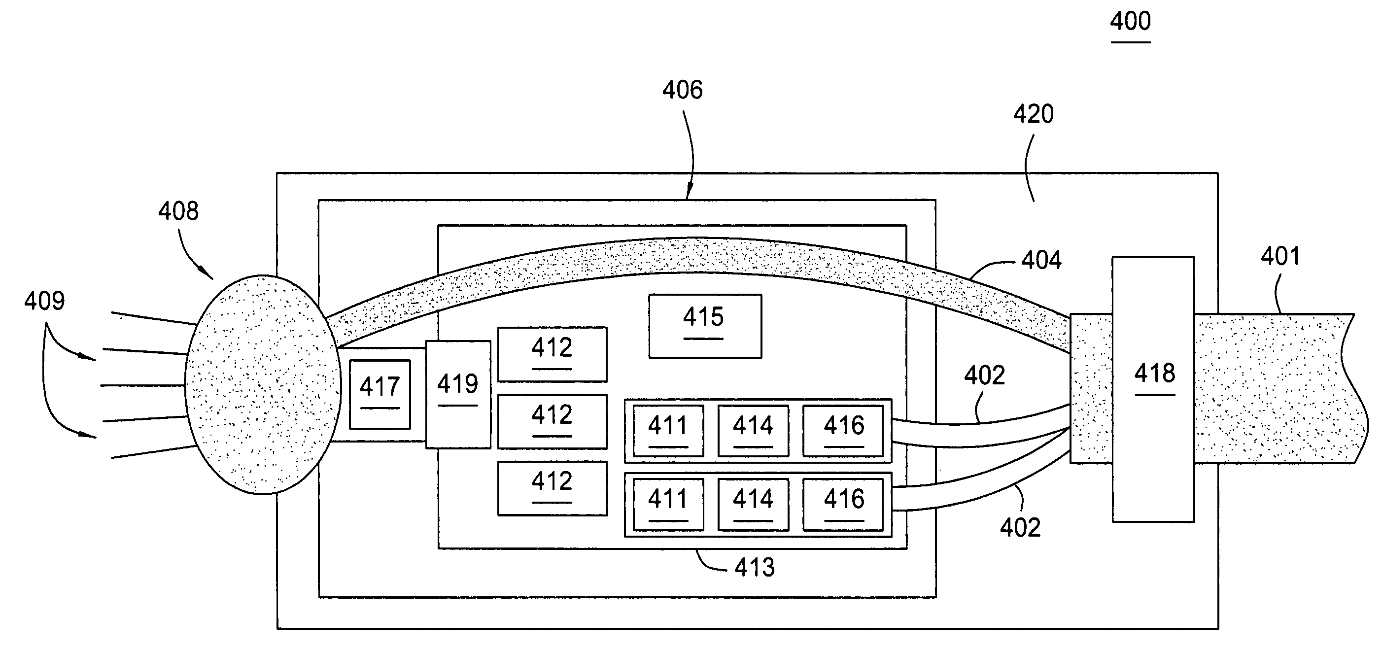
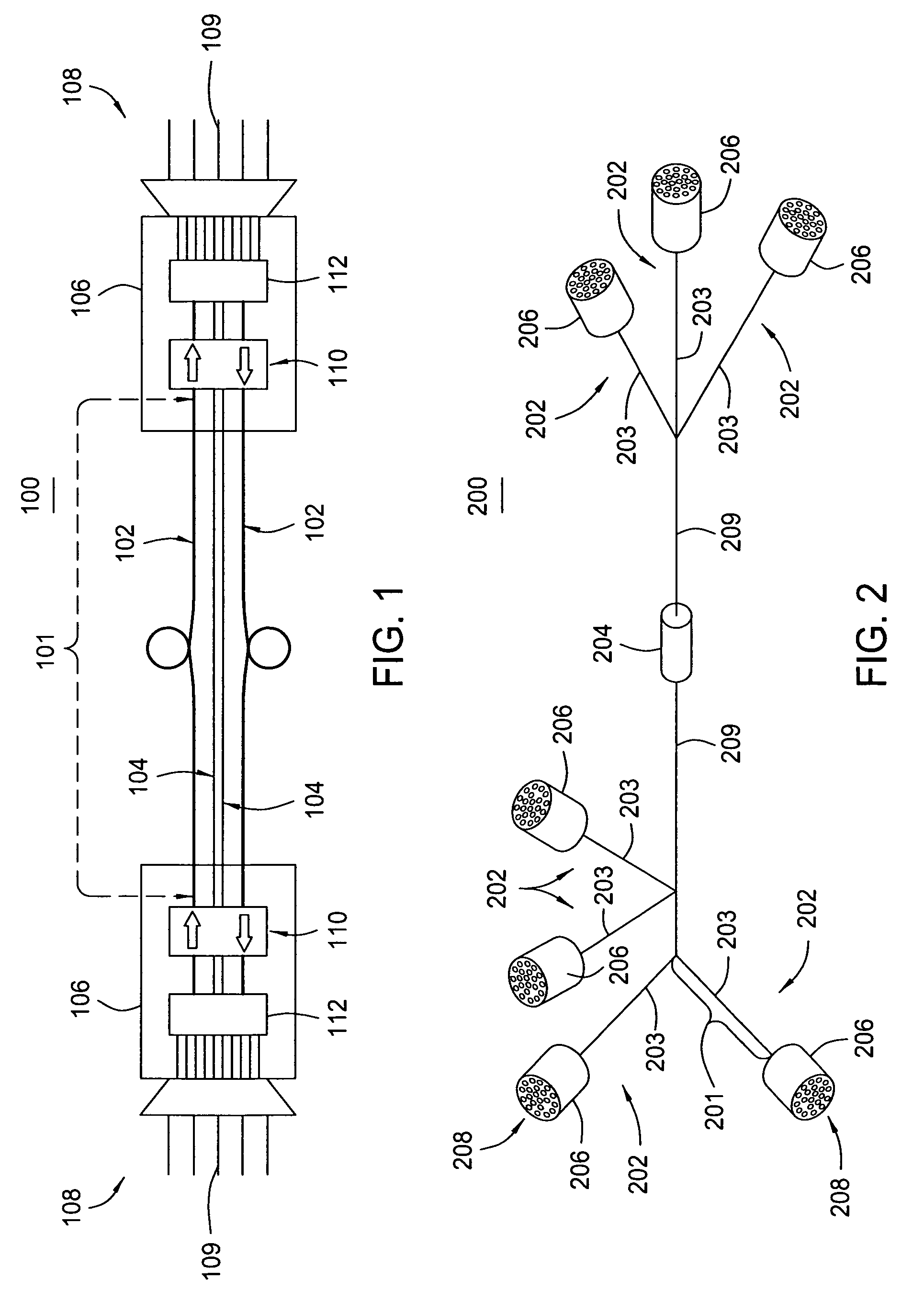
[0024]FIG. 1 illustrates an optical harness assembly 100 in accordance with an embodiment of the present invention. The harness assembly 100 includes an optical cable harness 101, which contains optical fibers 102 for carrying signals, and, alternatively, as a hybrid optical cable harness, may contain power conductors 104 for conducting power. The harness assembly 100 also includes active connector conversion units 106 coupled to the cable harness 101 at both ends, and electrical connectors or terminations 108, coupled to the active connector conversion units 106, also exemplary at both ends. The electrical connectors 108 each include connector pins 109 for conducting electrical signals to and from the terminal equipment.

[0025]Alternatively, the optical harness assembly 100 may contain an active connector conversion unit 106 and one electrical connector 108 coupled thereto on one end (i.e., the termination end) of the harness assembly 100, wherein the other end of the harness assemb...


PUM


Abstract

An optical harness assembly and method are provided. The optical harness assembly includes at least one optical harness cable having a termination end; at least one electrical connector having connector pins; and at least one active connector conversion unit coupled between the termination end of the optical harness cable and the electrical connector. A method for retrofitting an optical harness assembly into an existing platform is disclosed. The method includes removing a legacy wiring harness; installing an optical harness assembly having electrical connectors and an active connector conversion unit; and testing the compatibility of connector pins of the electrical connector to the active connector conversion unit. In another embodiment the method includes: identifying electrical signals present on each pin of each electrical connector presentation; programmatically adjusting an interface based on the identified electrical signals present; and mapping the electrical connector signals to digital signals. Alternatively, the method may further include: providing a personality adaptor coupled between the electrical connector pin outs and signal conditioners; configuring the personality adaptor based on the identified electrical signals present on each pin out of each electrical connector presentation; and providing configured electrical connector presentation signals to the interface.

Description

BACKGROUND[0001]1. Field of the Invention[0002]Embodiments of the present invention generally relate to wiring harnesses and methods and, more particularly, to optical harness assemblies and methods for retrofitting same into legacy systems.[0003]2. Description of the Related Art[0004]Vehicles, aircraft and watercraft, both commercial and military, include a wide range of onboard electrical and electronic equipment for command and control, communication and defense applications. Electrical (e.g., copper) wiring harnesses are commonly employed in such applications as part of the power distribution and communication network between and among the onboard hardware, such as terminal equipment or line-replaceable units (“LRUs”).[0005]Where factors such as weight, size, reliability, maintainability, supportability, environmental effects and total ownership costs are important, as in aircraft and watercraft platforms, electrical wiring harnesses have certain shortcomings. They are relativel...

Claims


Application Information

Patent Timeline
Patent Type & Authority Patents(United States)
IPC IPC(8): G02B6/36G02B6/44
CPCG02B6/4201G02B6/4472G02B6/4281G02B6/4416G02B6/4284
Inventor STARK, JASON BLAINLENZ, GADIJACKSON, BRADLEY SCOTT
Owner ZEPHYR PHOTONICS
Why Eureka
Try Eureka