Working system for circuit substrate

a working system and circuit technology, applied in metal-working equipment, metal-working equipment, manufacturing tools, etc., can solve the problems of limited freedom in selecting the location to dispose of the substrate supporting device, inconvenience of conventional stopper or sensor, and difficulty in so as to enhance the efficiency of mounting components and enhance the probability of reducing the total distance of movement of the component mounting head

Inactive Publication Date: 2008-04-29
FUJI CORP
View PDF26 Cites 7 Cited by
  • Summary
  • Abstract
  • Description
  • Claims
  • Application Information

AI Technical Summary

Benefits of technology

[0018]In a case where the first movable member is movable in the direction parallel to the conveying direction of the substrate conveyor and the substrate detector is held by the first movable member, the substrate detector is moved only in a direction parallel to the conveying direction. On the other hand, in a case where the substrate detector is held by the second movable member, the substrate detector can be moved in both of the directions parallel to and intersecting with (e.g. perpendicular to) the conveying direction. In the latter case where the second movable member is moved only in a direction parallel to the conveying direction, it is practically the same as that the substrate detector is held by the first movable member. However, when the second movable member is moved in the direction intersecting the conveying direction also, operation and effects obtained are different from those in the former case. For example, in the case where the circuit substrate has a cutout in its marginal portion on the downstream side in the conveying direction, the substrate detector can be moved to a location deviated from the cutout so that the presence of the cutout does not adversely influence the control of stopping the circuit substrate. Therefore, in the case where the substrate detector is moved in both of the directions parallel to and intersecting with the conveying direction, a freedom in detecting the circuit substrate is enhanced, particularly improving a freedom in the control of stopping the circuit substrate.
[0064]It may be arranged such that the circuit substrate is decelerated before being brought into contact with the stopper. For instance, in addition to the arrival detector, an approach detector may be employed to detect the circuit substrate coming close to the stopper so that the circuit substrate is decelerated upon detection of the circuit substrate approaching the stopper. Thus decelerating the circuit substrate lowers the undesirable impact of the circuit substrate being brought into contact with the stopper. For instance, in the case where electronic circuit components have been mounted on the circuit substrate but not fixed to the circuit substrate yet, displacement of the electronic circuit components from respective nominal positions caused upon stop of the circuit substrate, is avoided. The above mode (15) can be considered to be one example of the case where both the substrate detector and the stopper are employed by the working system described with respect to the mode (21) below. In this case, at least one of the arrival detector and the substrate detector corresponds to the substrate detector in the working system as described in the mode (21).

Problems solved by technology

However, whether disposed with the location fixed or adjustable, the conventional stopper or sensor suffers from an inconvenience as follows.
In such an arrangement, however, when the circuit substrate carried into the working system is a relatively small-sized circuit substrate, the circuit substrate is stopped in a marginal part of a range of movement of the working head (i.e., in an edge portion on the downstream side of the range), leading to many drawbacks which will be described later.
Although the stopper or sensor may be disposed such that the stopper or sensor is adjustable in location to avoid drawbacks which would be encountered in the case where the stopper or sensor is disposed with its location fixed, it is bothersome for the operator to adjust the location of the stopper or sensor.
Further, in a case where it is so arranged that the circuit substrate is supported from the under side by a substrate supporting device while the operation is performed on the circuit substrate, a freedom in selecting the location to dispose the substrate supporting device might be limited.

Method used


Image

  • Working system for circuit substrate
  • Working system for circuit substrate
  • Working system for circuit substrate

Examples


first embodiment

[0106]In this first embodiment, the electronic circuit components 16 supplied by the feeders 30 take the form of an electronic-circuit-component carrier tape accommodating a multiplicity of electronic circuit components arranged in a lengthwise direction of the tape at a predetermined pitch. The electronic-circuit-component carrier tape is accommodated in a tape accommodating device and fed by a tape feeder to feed the electronic circuit components 16 to the component supply portion. It is noted that the feeder may not be a tape feeder, but may be a bulk feeder which stores in bulk a number of electronic circuit components in a component-store device thereof, arranges the electronic circuit components into a single array, and supplies the electronic circuit components one by one from the component supply portion thereof by operation of a feeding device which uses vibration, an incline, airflow, conveyor belt or others, or a combination of some of these to feed the electronic circuit...

second embodiment

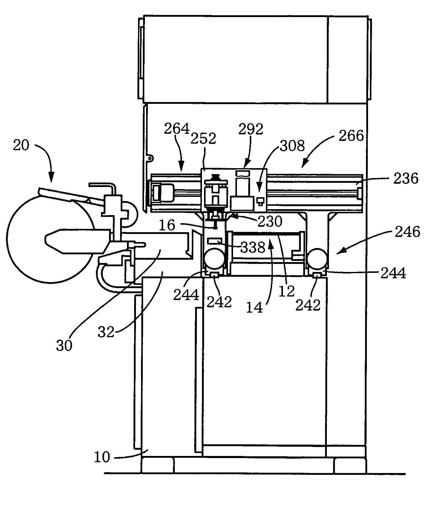
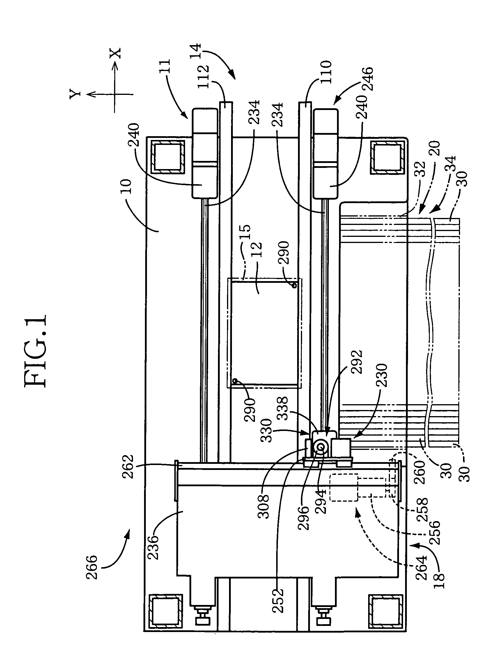
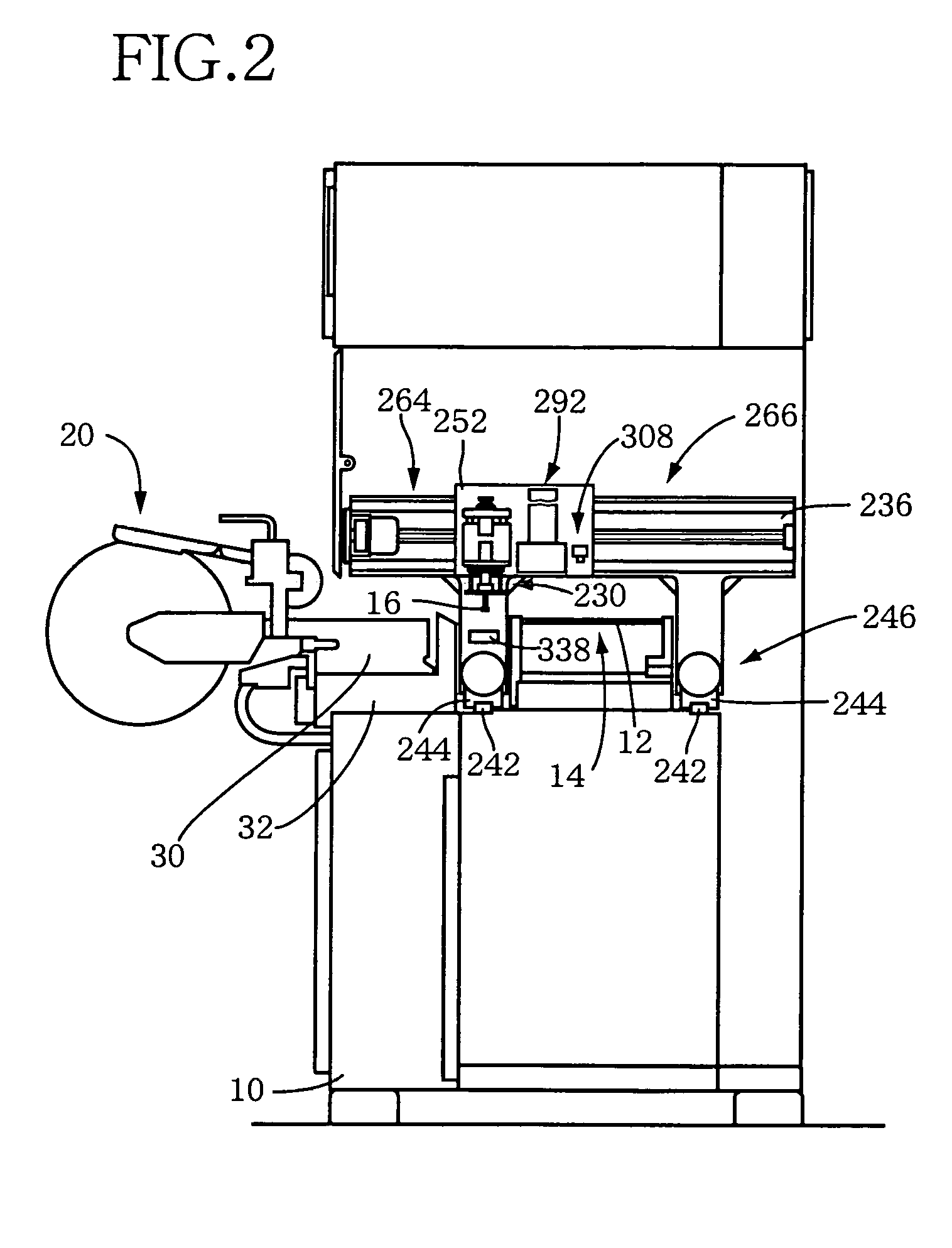
[0162]In an electronic-circuit-component mounting system 400 a component imaging system 402 is disposed with its location fixed, at a position which is between a component supplying device 20 and a PWB conveyor 14, and which is a center position of a range of movement of a component mounting head 230 in the direction in which the PWB conveyor 14 conveys the PWB 12. That is, the component imaging system 402 is located at a position corresponding to a center position of a row of component supply portions of a plurality of feeders 30. The component imaging system 402 has a component camera 404 as an imaging device and a lighting device 406, is located below a plane of movement of the component mounting head 230, and operates to take a front elevational image and a projective image of an object.

[0163]When the PWB 12 is stopped at the center position in the conveying direction, an entirety of the PWB 12 is positioned in the vicinity of the component imaging system 402, thereby improving...

third embodiment

[0165]In the embodiments described above, the predetermined detection portion of the PWB 12 is detected by the photoelectric sensors and then the PWB 12 is stopped. However, the detection may be implemented by taking an image with an imaging device, after which the PWB 12 is stopped. Such an embodiment (third embodiment) will be described by reference to FIGS. 16-18.

[0166]Except the control of stopping the PWB 12, an electronic-circuit-component mounting system 420 according to the third embodiment is constructed similarly to the electronic-circuit-component mounting system 11 as described above, and the similar part is not described here.

[0167]In the third embodiment, a fiducial-mark camera 294 of a fiducial-mark imaging system 292 takes an image of a downstream-side edge of a PWB 12 in a conveying direction so that the PWB 12 is detected, decelerated and stopped. That is, the imaging device for taking an image of a predetermined detection portion of the PWB 12 is adapted to take a...


PUM

PropertyMeasurementUnit
shapeaaaaaaaaaa
viscousaaaaaaaaaa
sizeaaaaaaaaaa

Abstract

A working system for a circuit substrate enabling a control of stopping the substrate without inconvenience. A PWB detector 308 held by a Y-axis slide 252 of an XY robot 266 moving a component mounting head, has reflection type photoelectric sensors 310, 312 spaced from each other in a direction of conveyance of a PWB 12 by a conveyor 14. When the PWB 12 carried in the system, the sensors 310, 312 are moved to a position corresponding to a downstream-side edge of the PWB 12 stopped at a predetermined stop position. The PWB 12 is decelerated when detected by one of the sensors on the upstream side, and stopped at a desired position regardless of its shape, dimensions and conveying direction, when detected by the other or downstream sensor. Electronic circuit components 16 can be supplied to plural kinds of PWBs 12 with one component supply device.

Description

TECHNICAL FIELD[0001]The present invention relates to a working system for a circuit substrate, in particular, to a control of stopping a circuit substrate conveyed by a substrate conveyor.BACKGROUND ART[0002]A working system for a circuit substrate is a system for performing a predetermined operation for a circuit substrate, and is, for example, an electronic-circuit-component mounting system for mounting electronic circuit components as components of an electronic circuit on a printed-wiring board, or a highly-viscous fluid coating system for coating a printed-wiring board with a highly viscous fluid such as an adhesive. As one kind of such a working system for a circuit substrate, there is known a system comprising: (a) a substrate conveyor capable of conveying a circuit substrate along a straight line in a conveying direction, and of stopping the circuit substrate at a desired position in the conveying direction; (b) a moving apparatus having a first movable member which is mova...

Claims


Application Information

Patent Timeline
Patent Type & Authority Patents(United States)
IPC IPC(8): B23P19/00H05K13/00
CPCH05K13/0061Y10T29/53187Y10T29/52Y10T29/53174Y10T29/53178Y10T29/53191
Inventor KONDO, TOSHIHIRO
Owner FUJI CORP
Why Eureka
Try Eureka