Constant flow valve assembly

Inactive Publication Date: 2008-04-29
GLOBAL AGRI TECH & ENG
View PDF60 Cites 60 Cited by
  • Summary
  • Abstract
  • Description
  • Claims
  • Application Information

AI Technical Summary

Problems solved by technology

While these known valves operate in an entirely satisfactory manner, for some uses, their design has proven to be overly complex, ex

Method used


Image

  • Constant flow valve assembly
  • Constant flow valve assembly
  • Constant flow valve assembly

Examples


Example

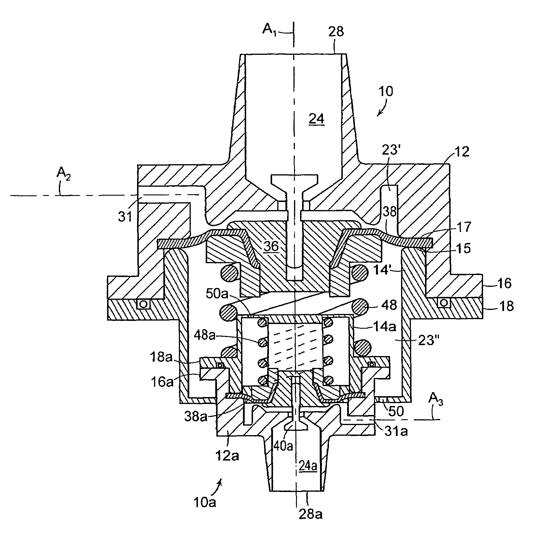
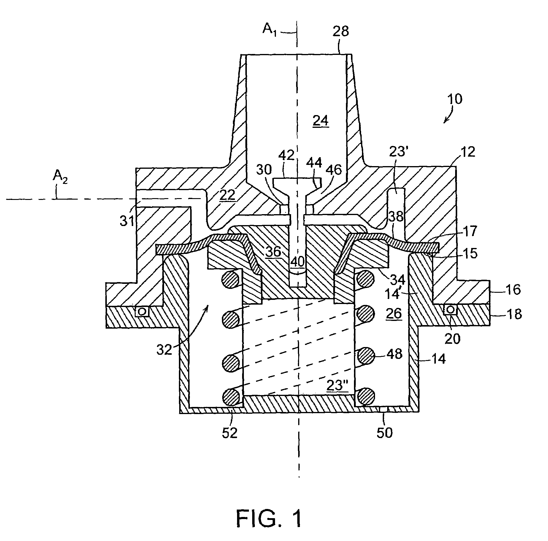
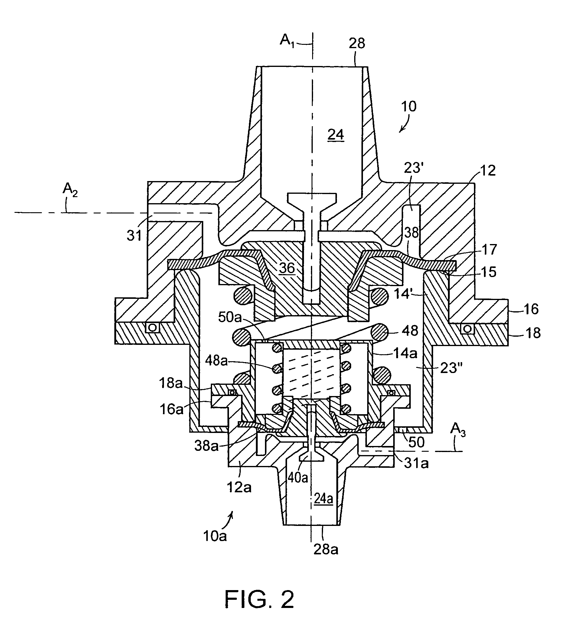
[0008]With reference initially to FIG. 1, a regulating valve of the type included in the combination of the present invention is generally depicted at 10. The valve includes an outer housing having a cap 12 joined to a cup-shaped base 14 at mating exterior flanges 16, 18, with an O-ring seal 20 interposed therebetween.

[0009]The housing is internally subdivided by a barrier wall 22 into a head section 24 and a base section 26. An inlet 28 is adapted to be connected to a fluid supply (not shown) having a pressure that can vary from below to above a threshold level. The inlet 28 and a central port 30 in the barrier wall 22 are aligned along a central axis A1 of the valve. An outlet port 31 is aligned on a second axis A2 transverse to the first axis A1.

[0010]A modulating assembly 32 cooperates with the barrier wall 22 to subdivide the base section into a fluid chamber 23′ segregated from a spring chamber 23″. The modulating assembly serves to prevent fluid flow through the valve when th...


PUM


Abstract

A dual valve assembly includes two regulating valves. Each valve includes an outer housing comprised of a cap joined to a base. The housing is internally subdivided by a barrier wall into a head section and a base section, the latter being further subdivided by a modulating assembly into a fluid chamber and a spring chamber. An inlet and a 90° outlet in the cap communicate with the fluid chamber. Fluid at a variable pressure is admitted into the fluid chamber via the inlet, with the modulating assembly serving to maintain the fluid exiting the fluid chamber via the outlet at a substantially constant pressure. A smaller one of the valves has its base nested within the spring chamber of the other larger valve.

Description

CROSS REFERENCE TO RELATED APPLICATION[0001]This application claims priority from Provisional Patent application Ser. No. 60 / 664,299 filed Mar. 22, 2005.BACKGROUND OF THE INVENTION[0002]1. Field of the Invention[0003]This invention relates to generally to fluid valves, and is concerned in particular with an assembly of regulating valves that are normally closed, that are opened by variable fluid pressures above selected threshold levels, and that when open, serve to deliver fluids at constant pressures and flow rates.[0004]2. Description of the Prior Art[0005]Regulating valves for the above-mentioned type are known, as disclosed for example in U.S. Pat. Nos. 6,026,850 and 6,209,578. While these known valves operate in an entirely satisfactory manner, for some uses, their design has proven to be overly complex, expensive, and difficult to incorporate in restricted spaces within fluid dispensing equipment, e.g., carbonated soft drink dispensers.BRIEF DESCRIPTION OF THE DRAWINGS[0006]F...

Claims


Application Information

Patent Timeline
IPC IPC(8): G05D16/08F16K27/02
CPCG05D16/0672Y10T137/5994Y10T137/7825Y10T137/87249Y10T137/7793Y10T137/7781
Inventor NEWTON, JOHN R.
Owner GLOBAL AGRI TECH & ENG
Why Eureka
Try Eureka