Compression ring for coaxial cable connector

a compression ring and coaxial cable technology, applied in the direction of connections, basic electric elements, electric devices, etc., can solve the problems of patent problems, connector disclosure, and a wide range of compression-type coaxial connectors in current use, and achieve the effect of facilitating deformation

Active Publication Date: 2008-04-29
HOLLAND ELECTRONICS
View PDF11 Cites 99 Cited by
  • Summary
  • Abstract
  • Description
  • Claims
  • Application Information

AI Technical Summary

Benefits of technology

[0017]More particularly, the compression ring of the present invention is a short tubular member having an axial lumen and an annular groove circumscribed around the outer surface thereof. The groove enables the radially inward deformation of the central portion of the axial lumen when a longitudinal compressive force is applied to the leading and trailing ends of the compression ring. The deformation of the ring over a cable forms a moisture-proof seal by the inward 360 degree ridge being formed by longitudinal force on the ring. The annular groove provides a pre-weakened portion to begin the deformation into a reduced ID circular ridge in the axial lumen. The material comprising the compression ring can be changed to support softer cables and harder ones. The ring closure method and seal differ from former ones by center-ring groove being forced to collapse into a seal by longitudinal force. Accordingly, it is unnecessary to include slots in the deformable compression ring to facilitate deformation. Such slots enable deformation of the compression member in response to a longitudinal force, but they do not provide a leakproof moisture seal. The present compression ring provides an annular mointure seal between the connector and the cable.

Problems solved by technology

The plethora of compression-type coaxial connectors in current use all have limitations with regard to accepting a restricted size range of cables and can only be used once.
In operation, the connector disclosed in the '076 patent has problems.
Burris has the difficulty of manufacture in that the groove needs to be made to a high tolerance to insure uniform compression, and the entire body (which is made from metal) needs to be annealed to effect compression at the groove / weakened location.
Another limitation is that upon compression of the body, it must be compressed evenly or the connector will not close properly.
The connector disclosed in the '076 patent has the problem of manufacturing precision grooves and consistent metal annealing to allow the longitudinally-moving shell to produce equal circumferenced inward protrusions.
If the heat treating is not perfect, too much force will be required to compress the outer shell of the connector thus making it difficult to use.
In addition, keeping the correct groove shape to have the protrusions move inwardly (versus collapse) is difficult.
The second problem with the compression-type connector disclosed in U.S. Pat. No. 5,525,076 is that the compression tools used to compress the securement member do not apply longitudinal force equally over the 360 degrees of the rear compression shell.
The limitation on the Holland design, where the ring is deformed in the rear only by a rear tapered shell ID, is that this bigger taper that is needed to compress the ring also restricts the maximum OD cable that may be used.
This has the limitations of having to also heat treat the entire body to effect a soft compression of the trailing edge.
It is also being limited as a one-use, connector.
The limitations of this design is that the force is very dependant upon the material of the ring being able to form an arc shape rather than assume the method of the Sterling.
Such slots enable deformation of the compression member in response to a longitudinal force, but they do not provide a leakproof moisture seal.

Method used


Image

  • Compression ring for coaxial cable connector
  • Compression ring for coaxial cable connector
  • Compression ring for coaxial cable connector

Examples


first embodiment

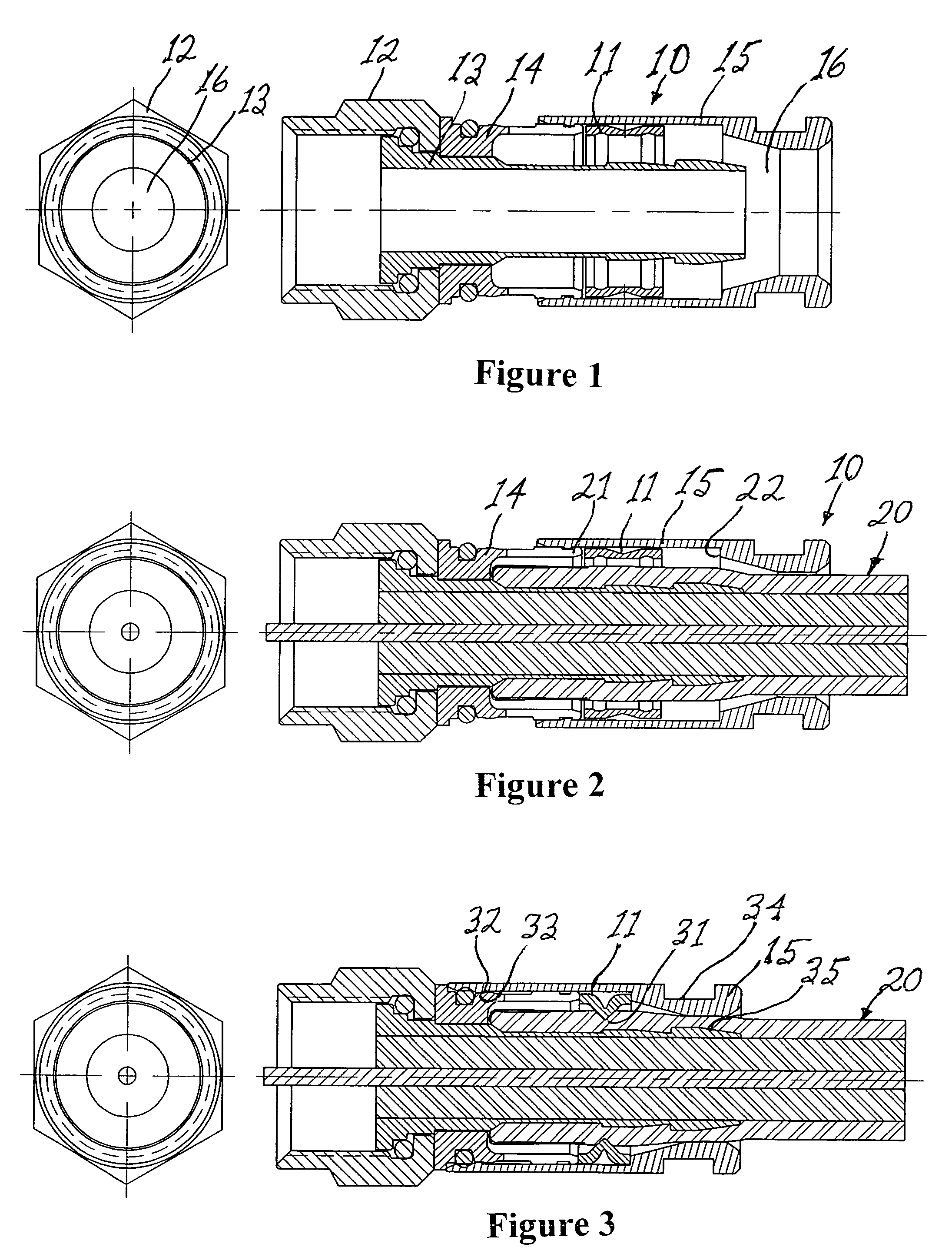
[0030]FIG. 1 is a longitudinal cross-sectional view of a coaxial cable connector 10 comprising a compression ring 11 in accordance with the present invention prior to attachment to the prepared end of a coaxial cable and in an uncompressed configuration. The connector 10 comprises a connector nut 12 having a tubular shank 13 extending rearwardly therefrom and a body portion 13 affixed to the connector nut and the tubular shank. An outer shell 15 having a central lumen 16 is slidably attached to the body portion 14 at the leading end thereof. The compression ring 11 of the present invention is removably disposed within the central lumen of the outer shell 15 rearward of the trailing end of the body portion 14.

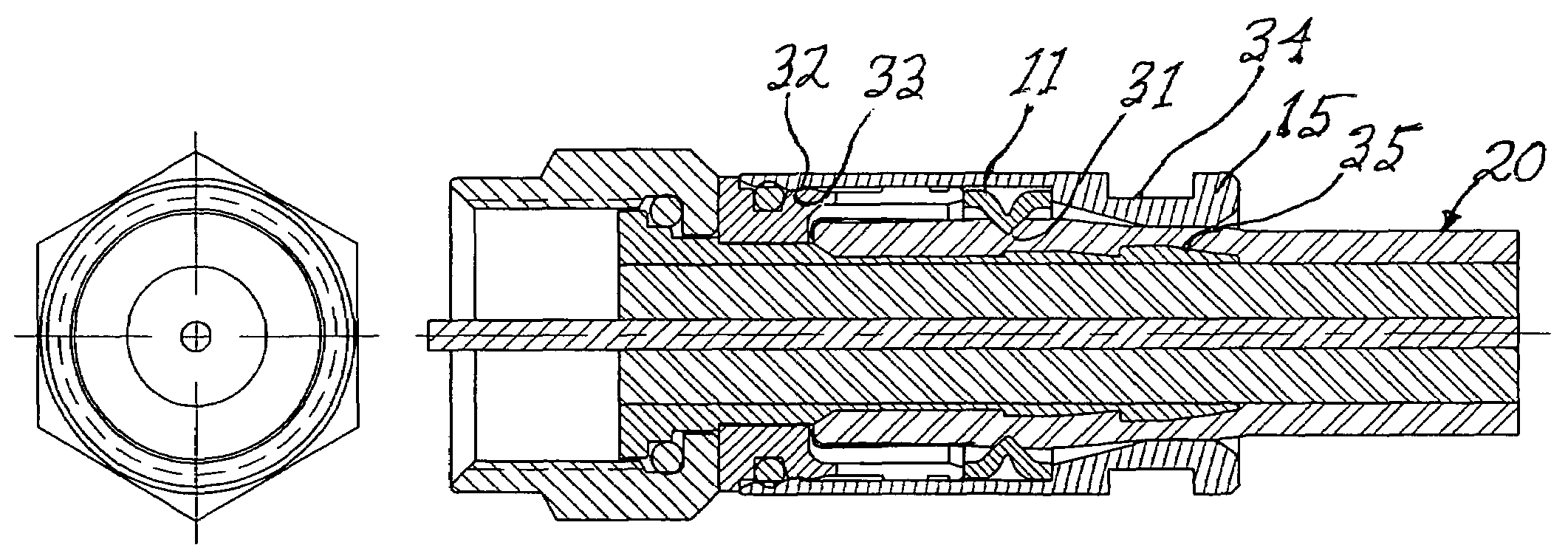
[0031]FIG. 2 is a longitudinal cross-sectional view of the coaxial cable connector 10 of FIG. 1 in the uncompressed configuration and showing the prepared end of a coaxial cable 20 inserted into the axial lumen 16 of the connector and fully advanced thereinto prior to attachment...

second embodiment

[0034]FIG. 7 is a partially cross-sectional side view of a coaxial cable connector 70 in accordance with the present invention. The connector 70 is shown in an open (i.e., noncompressed) position in FIG. 7. The connector 70 has a connector nut 71 on a leading end thereof and a centerpost 72 having a barb(s) 73 thereon. A hard rubber or plastic deformable tubular sleeve 74 has a leading end 75 that abuts the connector nut 71 and a trailing end in opposition thereto and a plurality of annular grooves 74a in the outer surface thereof. While the cross-sectional profile of the grooves 74a are illustrated as semicylindrical, it is understood that the groove profile can have other shapes such as being “V”-shaped”. A rigid, tubular shell 77 is slidable mounted on the outer surface of the sleeve 74. The shell 77 has a recurved trailing end 78 having a circular opening 79 therein, The opening 79 is dimensioned to accommodate the passage of the prepared end of a coaxial cable 90 (FIG. 9) there...


PUM


Abstract

The present invention discloses an improvement in coaxial compression connectors used in, inter alia, CATV, satellite, and home theater electronics. The present connectors accept a large range of cable sizes, allow replacement of the holding or compression element to accommodate a range of sizes, and allow the connector to be re-uesable. The connector comprises an attachment nut operable for electrically connecting the coaxial cable to another device, a tubular shank attached to the connector nut operable for accepting the dielectric layer of the coaxial cable therewithin, a body portion connecting the nut and tubular shank, a compression ring and an outer shell. In a first embodiment, the compression ring is a relatively short tubular member removably housed within the outer shell. The compression ring has an annular compression groove on the outer circumference thereof which causes a mid-portion of the ring to deform inwardly in response to a longitudinal force applied to opposing ends of the compression ring to securely hold the cable within the connector and create a 360 degree moisture seal. In a second embodiment, the body portion deforms inwardly. In both embodiments, a shoulder within the shell abuts the trailing end of the compressive member and exerts a longitudinal compression force thereon that causes the compressive member to circumferentially buckle inwardly against the cable.

Description

[0001]This application claims the benefit of U.S. Provisional Applications Ser. No. 60 / 797,322, filed May 2, 2006, and Ser. No. 60 / 842,994, filed Sep. 6, 2006.BACKGROUND OF THE INVENTION[0002]1. Field of the Invention[0003]The present invention relates to a deformable compression ring for use in a coaxial cable connector.[0004]2. Prior Art[0005]The plethora of compression-type coaxial connectors in current use all have limitations with regard to accepting a restricted size range of cables and can only be used once. Some connectors have the ability to exchange parts to adjust for out-of-size cables. The present art designs are one-time use. Due to the expense of many gold plated and specialty connectors now used in home theater and wireless and industrial applications, re-useability is a desirable feature when an error is made during installation.[0006]Burris, in U.S. Pat. No. 5,525,076, discloses a compression-type coaxial cable connector including an outer tubular member having an ...

Claims


Application Information

Patent Timeline
Patent Type & Authority Patents(United States)
IPC IPC(8): H01R9/05
CPCH01R9/0527
Inventor HOLLAND, MICHAEL
Owner HOLLAND ELECTRONICS
Why Eureka
Try Eureka