Integrated circuit testing module including data generator

Inactive Publication Date: 2008-04-29
CARR & FERRELL +1
View PDF19 Cites 37 Cited by
  • Summary
  • Abstract
  • Description
  • Claims
  • Application Information

AI Technical Summary

Benefits of technology

[0018]Various embodiments of the invention include a system comprising one or more input components configured to receive signals from an automated testing equipment at a first clock frequency, the automated testing equipment being configured to test an integrated circuit, an address generating component configured to generate addresses responsive to the signals received from the automated testing equipment, one or more data generating components configured to generate test data responsive to the signals received from the automated testing equipment, the test data to be delivered to the addresses generated by the address generating component, and one or more output components configured to convey the generated test data to the generated addresses within the integrated circuit at a second clock frequency, the integrated circuit being separable from the one or more output components, the second clock frequency being a higher frequency than the first clock frequency.
[0019]Various embodiments of the invention include a method comprising attaching an automated testing equipment to a test module, attaching an integrated circuit to be tested to the test module, configuring the test module for testing of the integrated circuit, receiving test signals from the automated testing equipment at the test module at a first clock frequency, generating test addresses within the test module responsive to the test signals received from the automated testing equipment, generating test data within

Problems solved by technology

BIST testing, however, is incomplete and does not test all aspects of the device's operation.
Thorough testing of an IC device is accomplished with complex and expensive external testing equipment.
As the complexity and clock speeds of integrated circuits increase, the capabilities of existing external testing equipment

Method used


Image

  • Integrated circuit testing module including data generator
  • Integrated circuit testing module including data generator
  • Integrated circuit testing module including data generator

Examples


Example

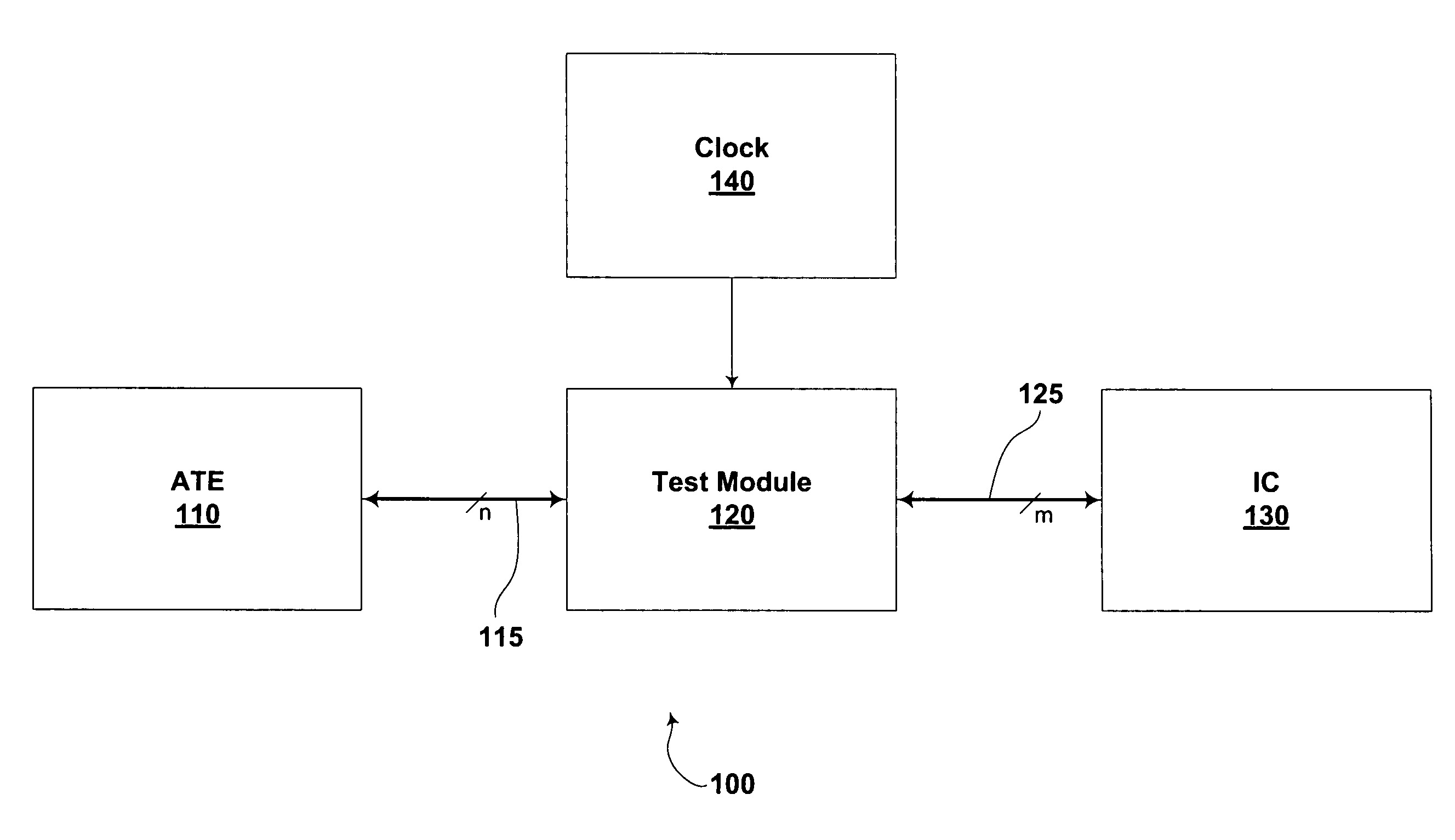
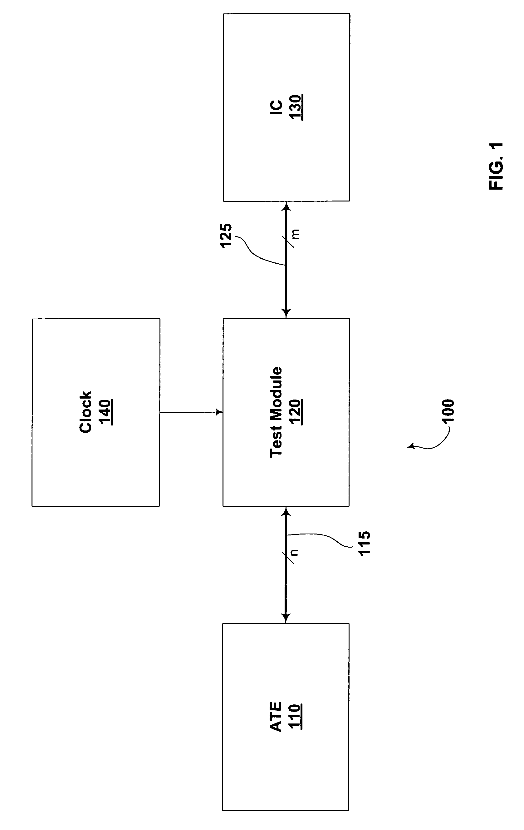
[0042]Various embodiments of the invention include a test module configured to operate between an automated testing equipment and one or more integrated circuits to be tested. The test module is configured to receive data, addresses and instructions from the automated testing equipment and to use these data and instructions to generate additional data and addresses. The test module is further configured to use the generated data and addresses to test the integrated circuit, to receive test results from the integrated circuit, and to report these test results to the automated testing equipment.

[0043]Communication between the automated testing equipment and the test module is optionally at a different clock frequency than communication between the test module and the integrated circuit being tested. As such, through the use of the test module, an automated testing equipment configured to operate at a first frequency can be used to test an integrated circuit at a second higher frequenc...


PUM


Abstract

Systems and methods of testing integrated circuits are disclosed. The systems include a test module configured to operate between an automated testing equipment and an integrated circuit to be tested. The testing interface is configured to test the integrated circuit at a higher clock frequency than the automated testing equipment is configured to operate. In order to do so, the testing interface includes components configured for generating addresses and test data to be provided to the integrated circuit. A variety of test data patterns can be produced and the test data can be address dependent.

Description

CROSS-REFERENCE TO RELATED APPLICATIONS[0001]The present application is a continuation of U.S. application Ser. No. 11 / 304,445, now U.S. Pat. No. 7,265,570 entitled “Integrated Circuit Testing Module” and filed on Dec. 14, 2005, which in turn is:[0002]a continuation-in-part of U.S. application Ser. No. 10 / 824,734, now U.S. Pat. No. 7,139,945 entitled “Chip Testing Within a Multi-Chip Semiconductor Package,” filed on Apr. 15, 2004;[0003]a continuation-in-part of U.S. application Ser. No. 10 / 870,365, now U.S. Pat. No. 7,103,815 entitled “Testing of Integrated Circuit Devices,” filed on Jun. 17, 2004, which is a continuation of U.S. application Ser. No. 09 / 967,389, filed on Sep. 28, 2001, now U.S. Pat. No. 6,754,866;[0004]a continuation-in-part of U.S. application Ser. No. 11 / 083,473 now U.S. Pat. No. 7,313,740 entitled “Internally Generating Patterns For Testing In An Integrated Circuit Device,” filed on Mar. 18, 2005, which is a continuation in part of U.S. application Ser. No. 10 / 20...

Claims


Application Information

Patent Timeline
IPC IPC(8): G01R31/26
CPCG01R31/31922G11C29/56G11C29/56004G11C29/56012G11C2029/5602G11C2029/5606
Inventor ONG, ADRIAN E.
Owner CARR & FERRELL
Why Eureka
Try Eureka