Autofocus method and apparatus

a technology of autofocus and focusing aids, applied in the field of autofocus methods and focusing devices, can solve the problems of undesirable movement of the lens to a hyperfocal position, and achieve the effect of fine adjustment and easy notification

Inactive Publication Date: 2008-04-29
CANON KK
View PDF18 Cites 25 Cited by
  • Summary
  • Abstract
  • Description
  • Claims
  • Application Information

AI Technical Summary

Benefits of technology

[0014]According to the present invention, the focus can be finely adjusted by performing autofocus operation using, as a scan range, a narrow range before and after a focus position adjusted to a certain degree by the photographer in manual focusing. When focusing is incapable, the focus lens is driven to a position before the start of autofocusing. Even if, therefore, focusing is incapable, the focus position does not greatly deviate from a focus adjusted to a certain degree by the photographer.
[0015]The in-focus display and in-focus sound are changed between normal autofocusing and fine autofocusing in manual focusing. The photographer can be easily notified of the current focus mode setting. In addition, the scan range of fine autofocusing in manual focusing is changed in accordance with the zoom lens position. The focus can be adjusted to an object at the same distance regardless of the zoom lens position.

Problems solved by technology

In this case, if the in-focus position cannot be calculated due to low object contrast upon autofocusing, the lens is undesirably moved to a hyperfocal position.

Method used


Image

  • Autofocus method and apparatus
  • Autofocus method and apparatus
  • Autofocus method and apparatus

Examples


first embodiment

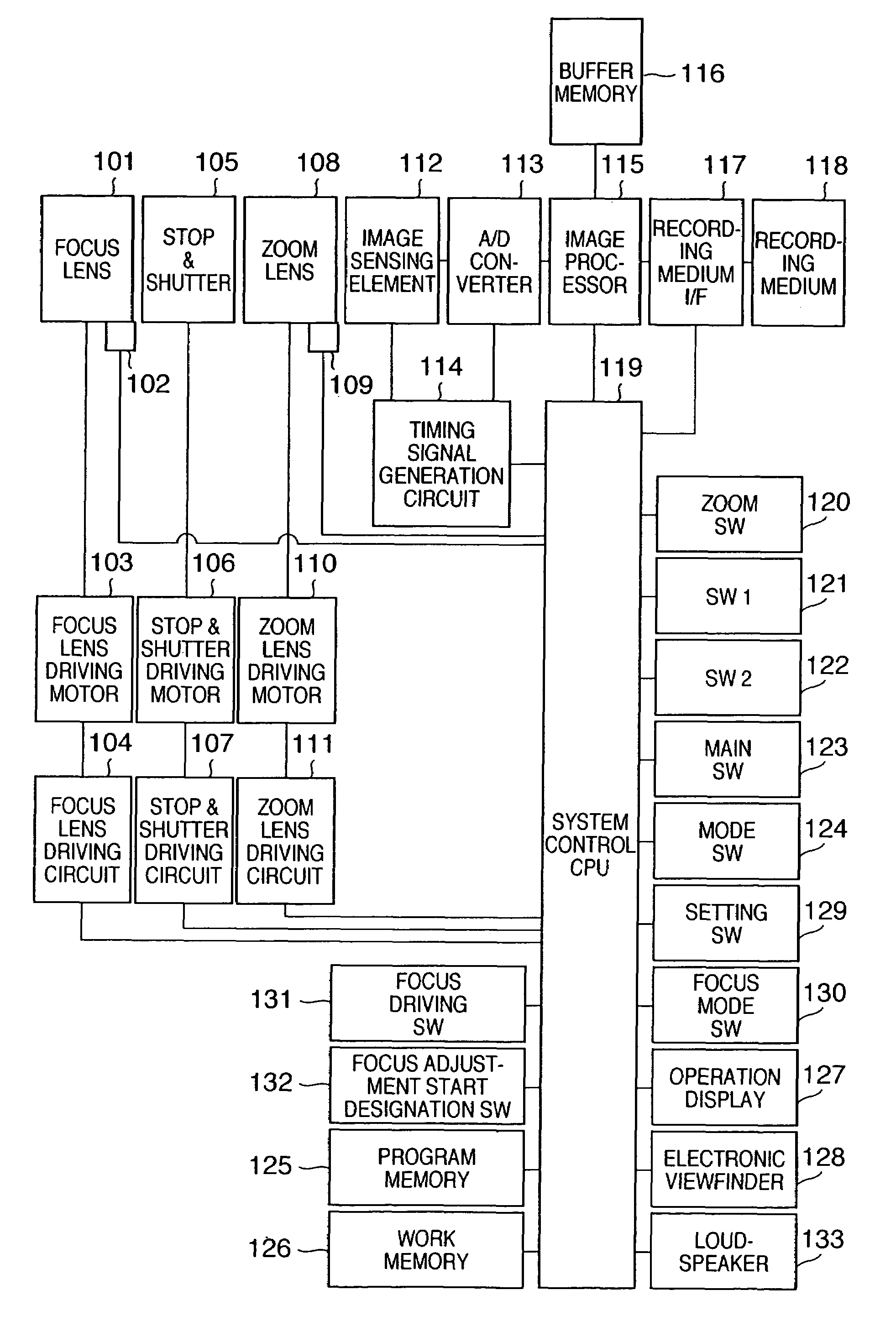
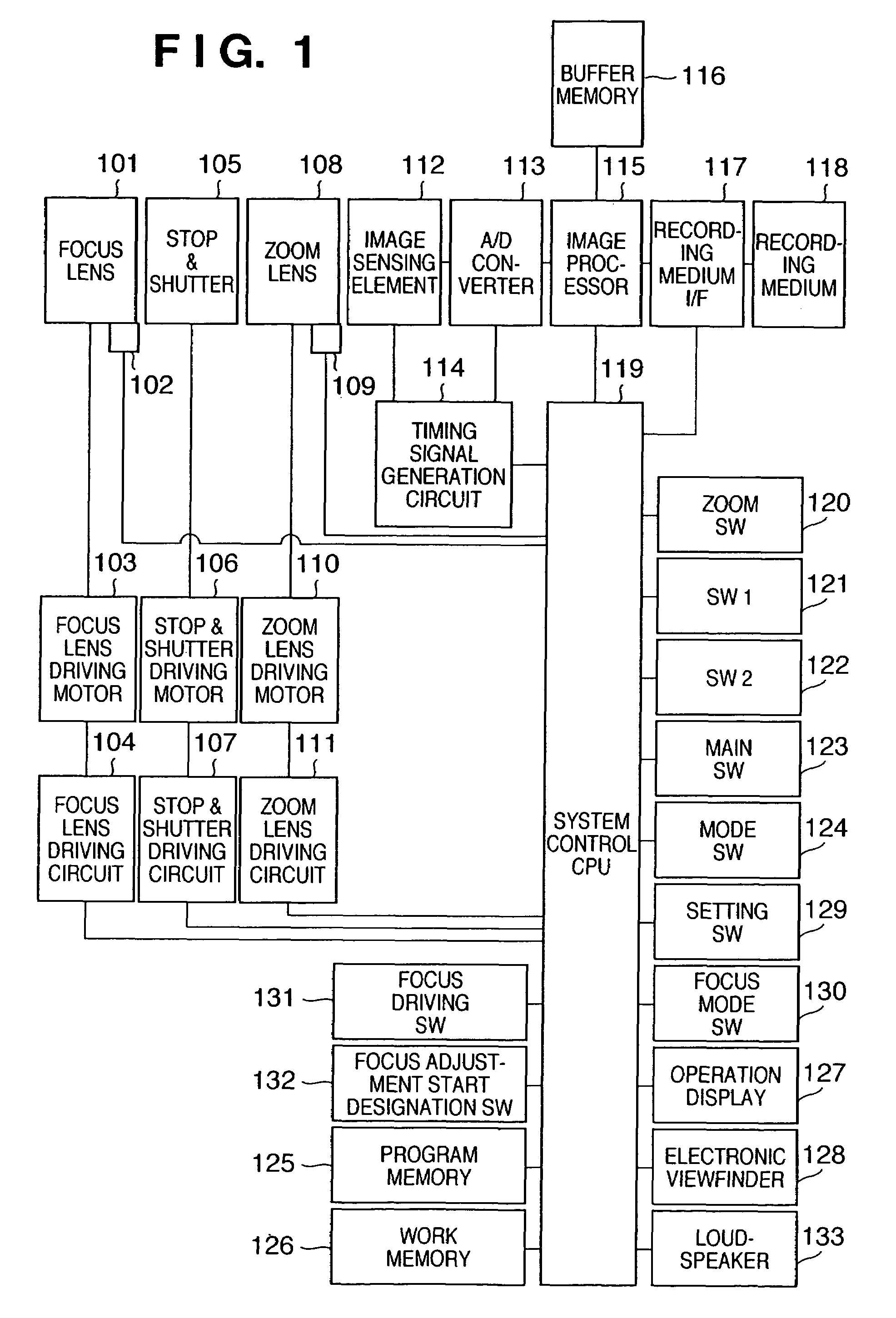
[0032]FIG. 1 is a block diagram showing a digital camera to which the present invention is applied. Reference numeral 101 denotes a focus lens for adjusting the focus onto an image sensing element to be described later; 102, a photointerrupter which detects the initial position of the focus lens 101; 103, a motor which drives the focus lens 101; 104, a focus lens driving circuit which inputs a driving signal to the motor 103 to move the focus lens 101; 105, a light quantity control member such as a stop and shutter; 106, a motor which drives the stop & shutter 105; 107, a stop & shutter driving circuit which inputs a driving signal to the motor 106 to move the stop & shutter 105; 108, a zoom lens which changes the focal length of a photographing lens; 109, a photointerrupter which detects the initial position of the zoom lens 108; 110, a motor which drives the zoom lens 108; and 111, a zoom lens driving circuit which inputs a driving signal to the motor 110 to move the zoom lens 108...

second embodiment

[0056]In the above description, one scan start position, one scan end position, and one scan interval are set when the focus mode is the manual focus mode. The scan start position, scan end position, and scan interval may be changed in accordance with the position of the zoom lens 108. Processing for this setting will be explained.

[0057]FIG. 10 corresponds to the flow chart for explaining setting of the distance measurement range in FIG. 6 according to the first embodiment. In step S1001, whether the focus mode has been set to manual focusing by a focus mode SW 130 is determined. If YES in step S1001, the flow advances to step S1002; if NO, to step S1009. In step S1002, whether the position of a zoom lens 108 is “wide” is determined. If YES in step S1002, the flow advances to step S1003; if NO, to step S1006.

[0058]In step S1003, the scan start position is set to PSW1. In step S1004, the scan end position is set to PEW1. In step S1005, the scan interval as a focus lens position inter...


PUM


Abstract

An object of this invention is to provide an autofocus method and apparatus capable of always performing proper focusing operation. To achieve this object, a control device drives a focus lens in accordance with the operation of an operation device, and stores the stop position of the focus lens. While the focus lens is driven within a predetermined range using the stop position as a reference, the control device stores an output from an extraction device in association with the position of the focus lens. The control device determines the focusing state of the focus lens from the output from the extraction device, and when determining from the determination result that the focus lens is incapable of focusing, drives the focus lens to the stop position.

Description

FIELD OF THE INVENTION[0001]The present invention relates to an autofocus method and apparatus in an image sensing apparatus such as an electronic still camera.BACKGROUND OF THE INVENTION[0002]In an autofocus apparatus such as an electronic still camera or video camera, a lens position where the high-frequency component of a luminance signal obtained from an image sensing element such as a CCD maximizes is set as an in-focus position. Known examples of this method are a hill-climbing method of moving the lens in a direction in which the high-frequency component (to be referred to as a focus evaluation value hereinafter) of a luminance signal obtained from an image sensing element and setting as an in-focus position a position where the focus evaluation value maximizes, and a scan method of storing focus evaluation values while driving the lens in the entire distance measurement range and setting as an in-focus position a lens position corresponding to the maximum value among stored ...

Claims


Application Information

Patent Timeline
Patent Type & Authority Patents(United States)
IPC IPC(8): H04N5/232H04N5/222G03B13/36G02B7/08G02B7/28G02B7/36G03B17/12G03B17/18H04N5/225
CPCH04N5/23212H04N23/673H04N23/633
Inventor OGINO, HIROYUKI
Owner CANON KK
Why Eureka
Try Eureka