Network traffic synchronization mechanism

a network traffic and synchronization mechanism technology, applied in the field of computer networks, can solve problems such as affecting data transfer speed,

Active Publication Date: 2008-04-29
CA TECH INC
View PDF2 Cites 73 Cited by
  • Summary
  • Abstract
  • Description
  • Claims
  • Application Information

AI Technical Summary

Benefits of technology

[0028]The present invention provides methods, apparatuses and systems directed to a network traffic synchronization mechanism facilitating the deployment of network devices in redundant network topologies. In certain embodiments, when a first network device directly receives network traffic, it copies the network traffic and transmits it to at least one partner network device. The partner network device processes the copied network traffic, just as if it had received it directly, but, in one embodiment, discards the traffic before forwarding it on to its destination. In one embodiment, the partner network devices are operative to exchange directly received network traffic. As a result, the present invention provides enhanced reliability and seamless failover. Each unit, for example, is ready at any time to take over for the other unit should a failure occur. As discussed below, the network traffic synchronization mechanism can be applied to a variety of network devices, such as firewalls, gateways, network routers, and bandwidth management devices.

Problems solved by technology

While there are certain perceived advantages, this characteristic has the consequence of juxtaposing very high-speed packets and very low-speed packets in potential conflict and produces certain inefficiencies.
Certain loading conditions degrade performance of networked applications and can even cause instabilities which could lead to overloads that could stop data transfer temporarily.
The problem with this approach is that, while network access is preserved, there is no failover mechanism to control or optimize network traffic while the bandwidth management device 130 remains down.
While the hot standby feature is suitable in shared Ethernet environments, the use of Ethernet LAN switches in more modern enterprise networks has presented further challenges.
Furthermore, many enterprise network architectures feature redundant topologies for such purposes as load-sharing and failover.
This circumstance renders control of network traffic on a network-wide basis problematic, especially when the bandwidth management devices 30a, 30b each encounter only part of the network traffic.
This circumstance often renders it impossible to adequately classify data flows associated with connections active at the time of a change or failover in the active bandwidth management device.

Method used


Image

  • Network traffic synchronization mechanism
  • Network traffic synchronization mechanism
  • Network traffic synchronization mechanism

Examples


Embodiment Construction

)

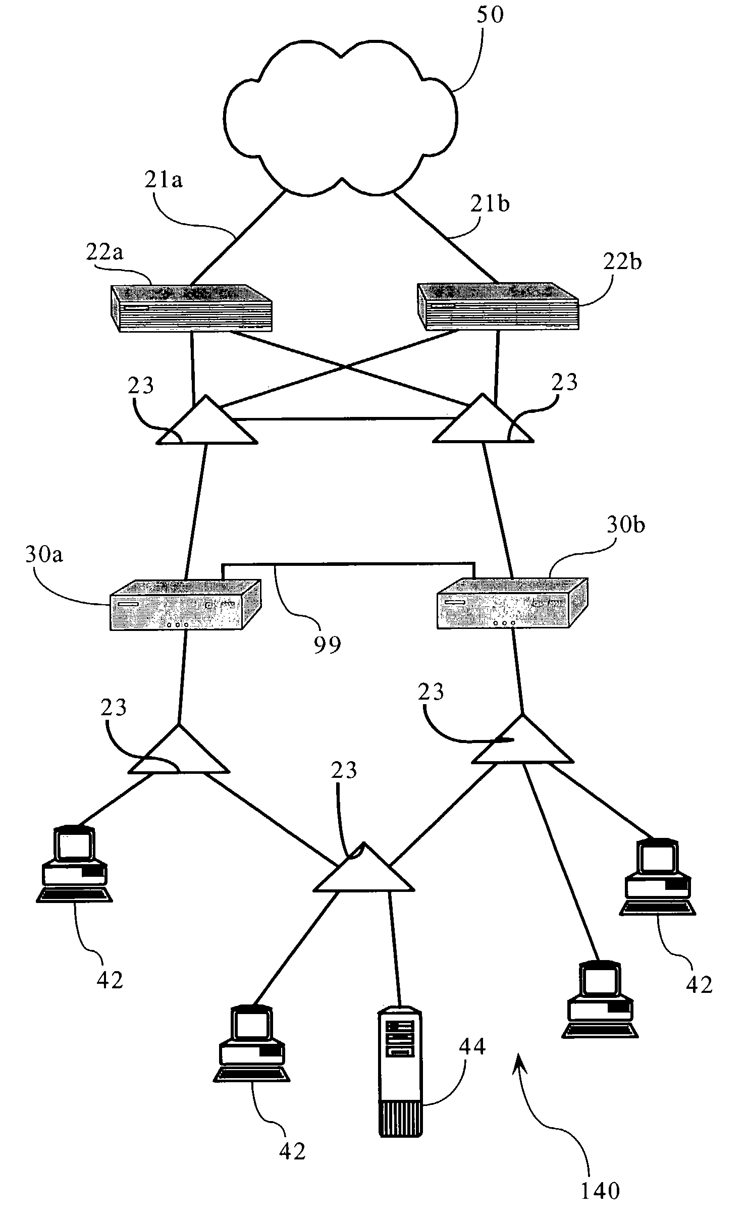
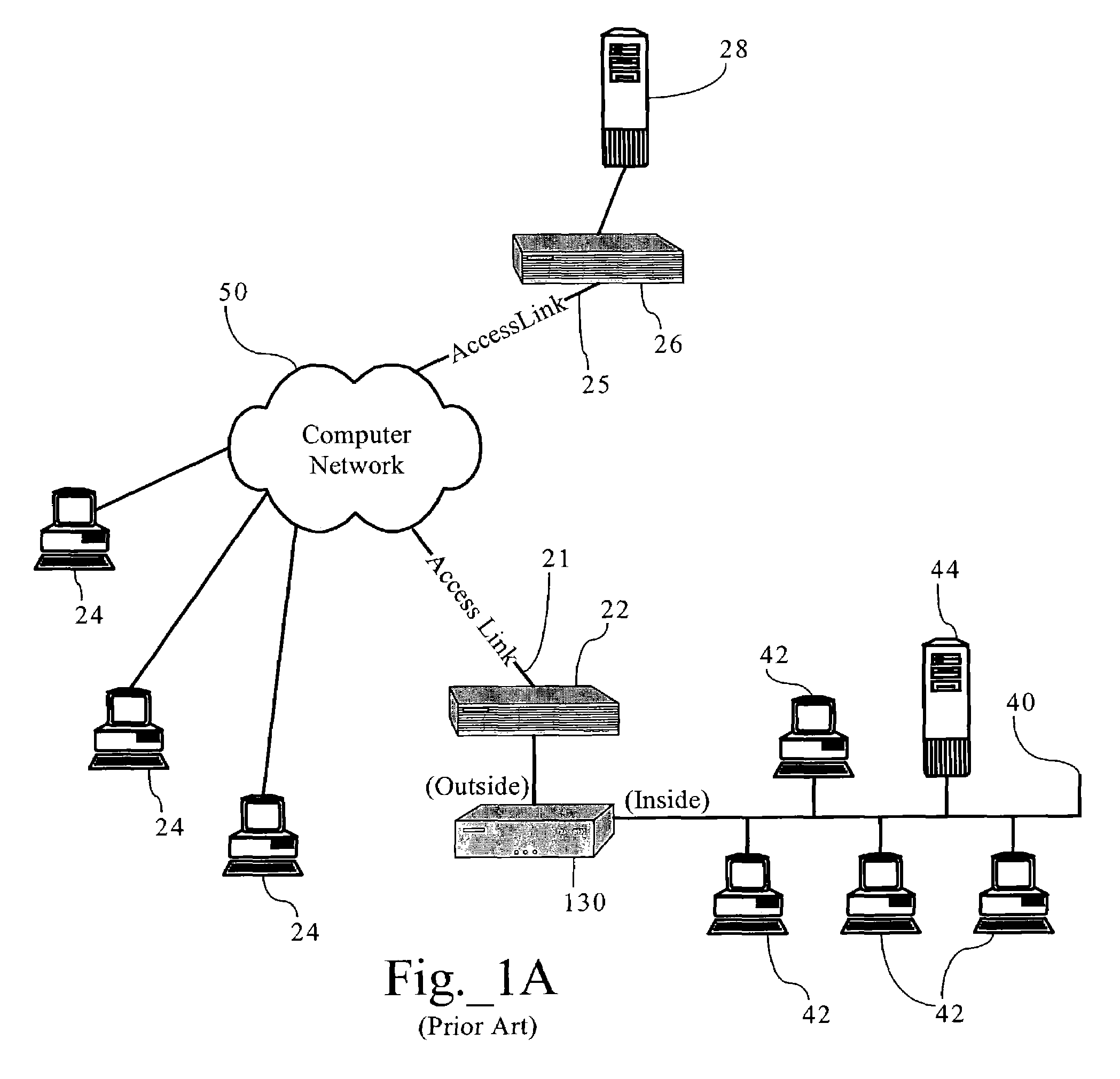
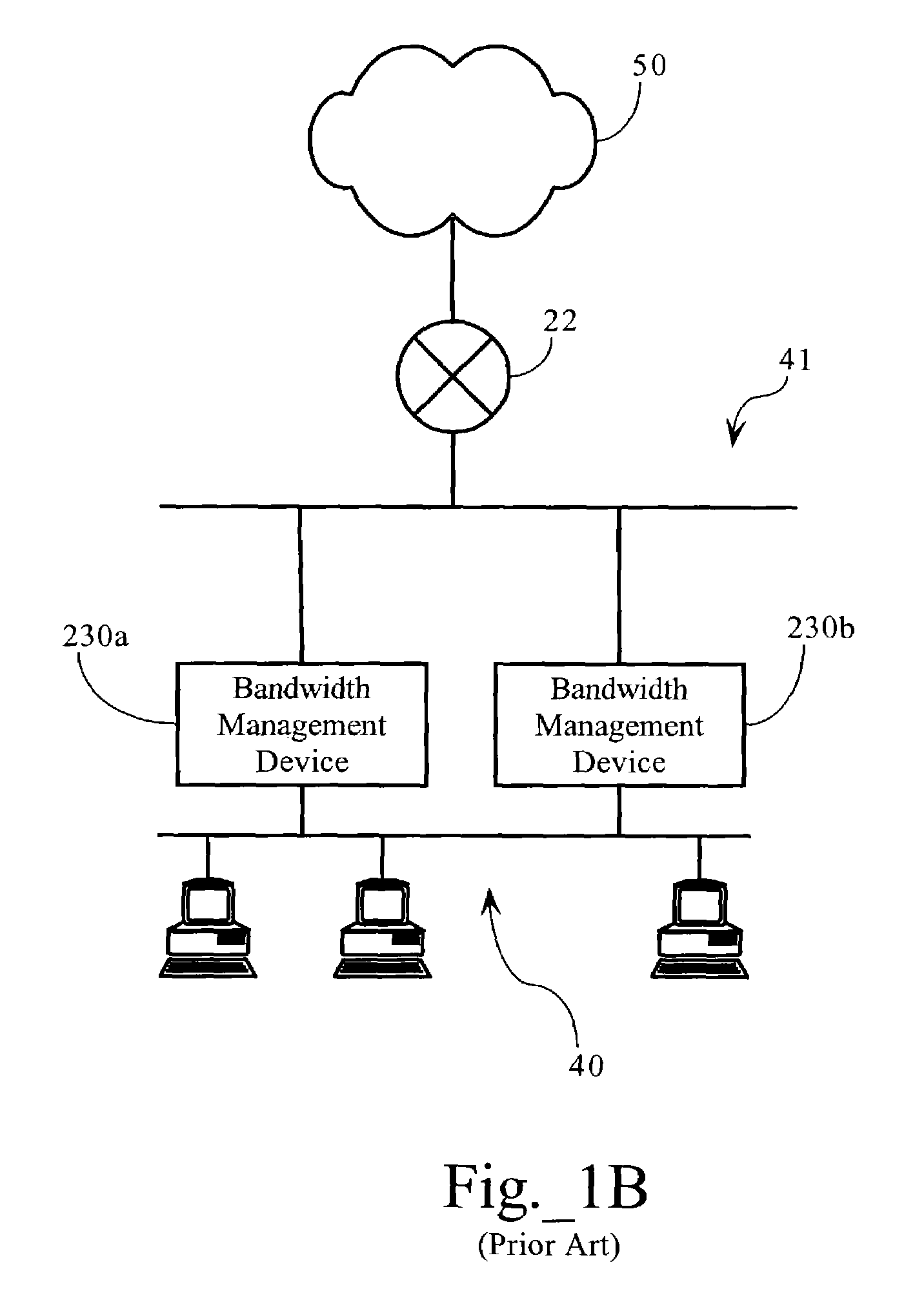
[0041]FIGS. 2A and 2B illustrate two possible network environments in which embodiments of the present invention may operate. FIG. 2A illustrates a computer network environment where access link 21 and router 22 connect LAN 40 to computer network 50. As FIG. 2A shows, the network environment includes redundant network devices 30a, 30b operatively connected to communication paths between LAN 40 and router 22 via LAN switches 23. FIG. 2B illustrates a computer network environment featuring a redundant network topology, that includes first and second access links 21a, 21b; routers 22a, 22b; and network devices 30a, 30b. Access links 21a, 21b operably connect computer network 140 to computer network 50. In one embodiment, computer network 140 is an enterprise WAN comprising a plurality of LAN segments. In one embodiment, computer network 50 is an open computer network, such as the Internet. As one skilled in the art will recognize, the network topology can be expanded to include additi...


PUM


Abstract

Methods, apparatuses and systems directed to a network traffic synchronization mechanism facilitating the deployment of network devices in redundant network topologies. In certain embodiments, when a first network device directly receives network traffic, it copies the network traffic and transmits it to at least one partner network device. The partner network device processes the copied network traffic, just as if it had received it directly, but, in one embodiment, discards the traffic before forwarding it on to its destination. In one embodiment, the partner network devices are operative to exchange directly received network traffic. As a result, the present invention provides enhanced reliability and seamless failover. Each unit, for example, is ready at any time to take over for the other unit should a failure occur. As discussed below, the network traffic synchronization mechanism can be applied to a variety of network devices, such as firewalls, gateways, network routers, and bandwidth management devices.

Description

CROSS-REFERENCE TO RELATED APPLICATIONS[0001]This application makes reference to the following commonly owned U.S. patent applications and patents, which are incorporated herein by reference in their entirety for alt purposes:[0002]U.S. patent application Ser. No. 08 / 762,828 now U.S. Pat. No. 5,802,106 in the name of Robert L. Packer, entitled “Method for Rapid Data Rate Detection in a Packet Communication Environment Without Data Rate Supervision;”[0003]U.S. patent application Ser. No. 08 / 970,693 now U.S. Pat. No. 6,018,516, in the name of Robert L. Packer, entitled “Method for Minimizing Unneeded Retransmission of Packets in a Packet Communication Environment Supporting a Plurality of Data Link Rates;”[0004]U.S. patent application Ser. No. 08 / 742,994 now U.S. Pat. No. 6,038,216, in the name of Robert L. Packer, entitled “Method for Explicit Data Rate Control in a Packet Communication Environment without Data Rate Supervision;”[0005]U.S. patent application Ser. No. 09 / 977,642 now U...

Claims


Application Information

Patent Timeline
Patent Type & Authority Patents(United States)
IPC IPC(8): H04J3/14H04J3/06H04L12/26H04L12/28H04L12/56
CPCH04L41/0896H04L45/00H04L45/586H04L41/0893H04L41/0894
Inventor VARIER, ROOPESH R.JACOBSON, DAVIDRIDDLE, GUY
Owner CA TECH INC
Why Eureka
Try Eureka