Optical watermark

Inactive Publication Date: 2008-04-29
TRUSTCOPY PTE
View PDF22 Cites 39 Cited by
  • Summary
  • Abstract
  • Description
  • Claims
  • Application Information

AI Technical Summary

Benefits of technology

[0015]Because the superposition of multiple layers is a non-inversable process, the complicity of the optical watermark increases and it is very difficult, if not impossible, to reverse engineer to derive the parameters and hidden information from the watermark. Because there are multiple layers, diff

Problems solved by technology

Without knowing all the secrets (including latent image objects and parameters of the dot patterns) of the optical watermark

Method used


Image

  • Optical watermark
  • Optical watermark
  • Optical watermark

Examples


Example

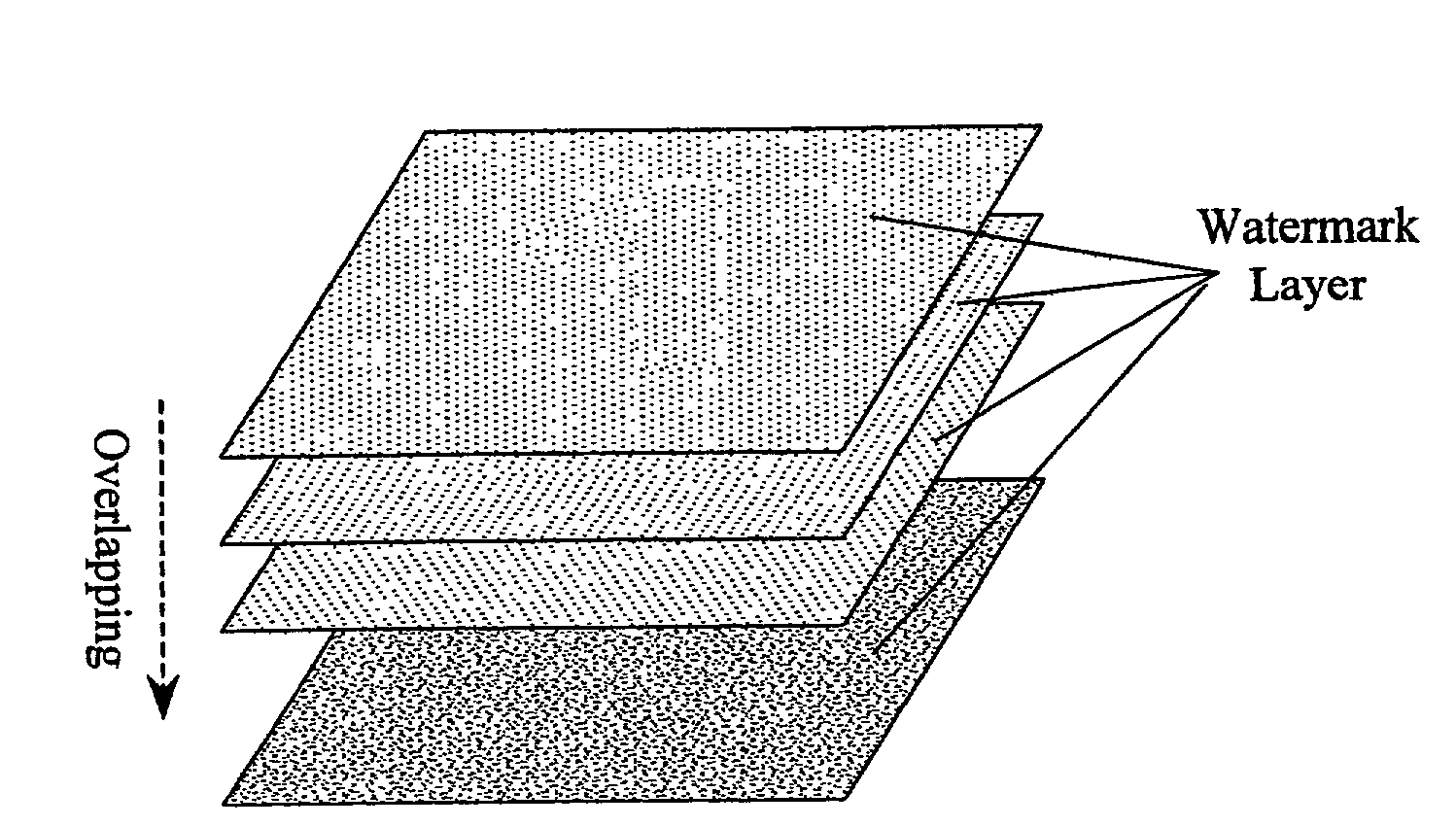
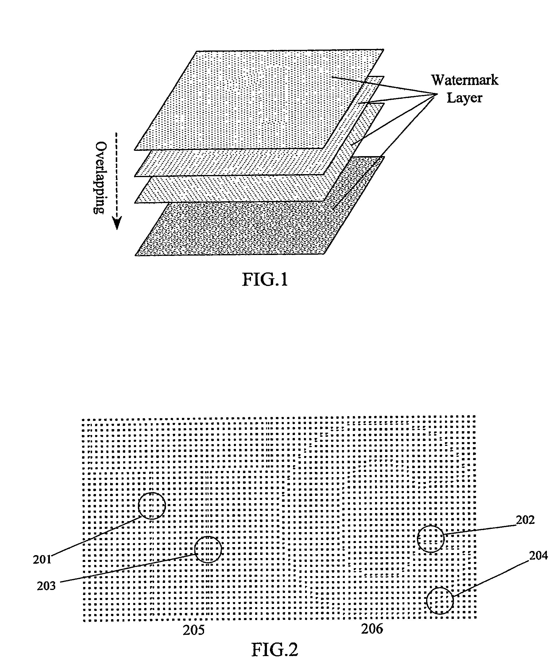
[0025]The optical watermark in this invention has a multiple layered structure as shown in FIG. 1. Watermark layers are superposed on each other to provide multiple layers and categories of protection. This superposition of several layers means that it is very difficult, if not impossible, to derive the parameters of the structure and the hidden information from the optical watermark alone.

[0026]Each watermark layer is a repetitive structured array of dots. Latent image objects are embedded into the watermark layer by modulation. This may include, for example, phase modulation. The structure and orientation of the different watermark layers in an optical watermark must be different from each other. Only the decoder corresponding to a particular watermark layer can be used to view the latent image object embedded in that particular watermark layer.

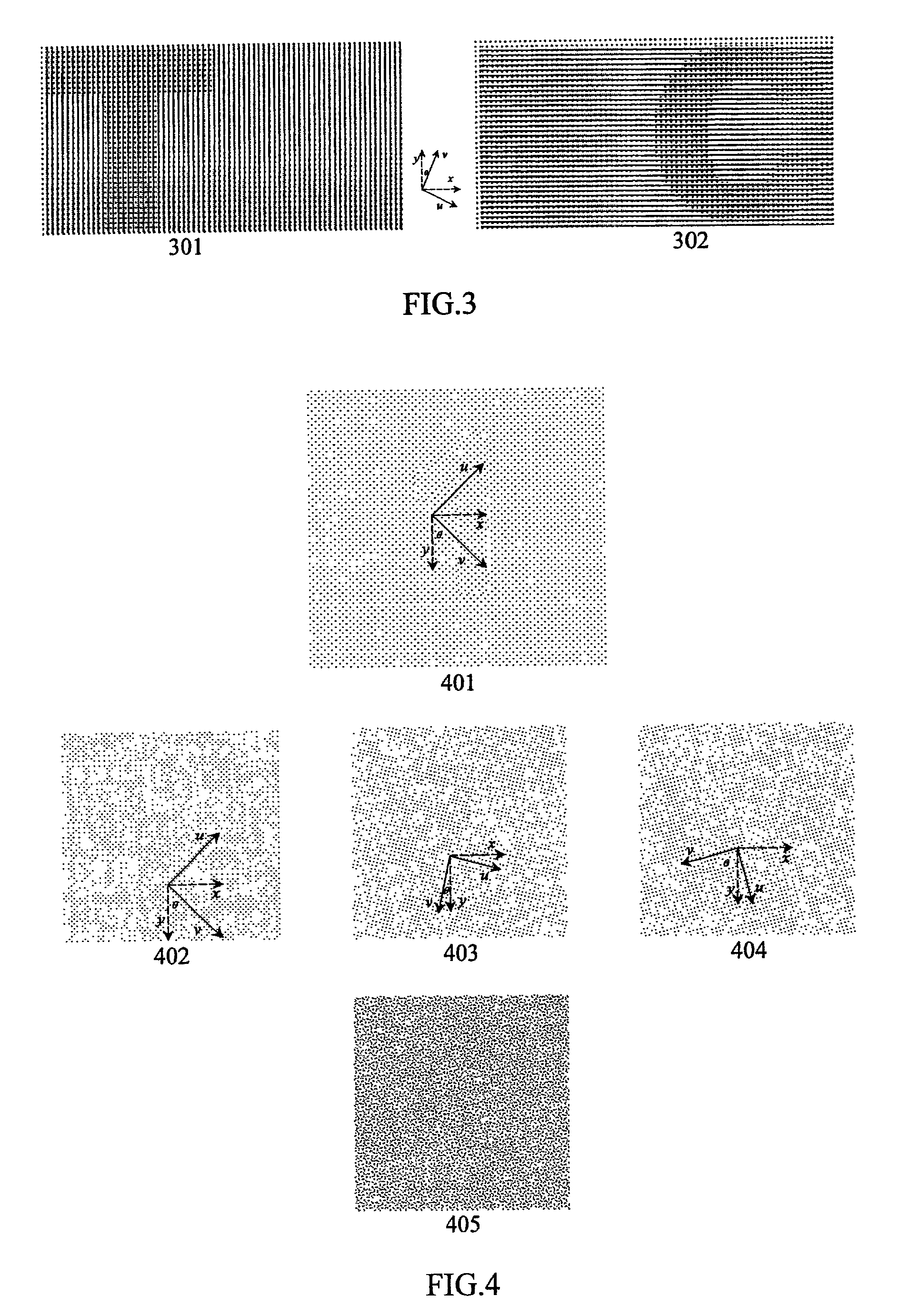
Basic watermark layer-2-D dot arrays

[0027]The basic watermark layer is a 2-D dot array, varying in two orthogonal directions. To embed lat...


PUM


Abstract

A multiple-layered watermark is generated to be placed on document, to protect against counterfeiting and forgery. Hidden information embedded into each of the watermark's layers is only detectable by using a corresponding decoder. Because of the multiple-layered structure, it is difficult to reverse engineer the optical watermark. The generalized watermark structure significantly increases the “key space” of the decoder.

Description

[0001]This application is a continuation-in-part of international application number PCT / SG00 / 00147, filed 15 Sep. 2000, pending.FIELD OF THE INVENTION[0002]This invention generally relates to a method and apparatus for producing optical watermarks on printed and electronic documents.DEFINITION[0003]Throughout this specification or reference to a document is to be taken as including a printed document and / or an electronic document and / or a copy (printed or electronic) of a printed document and / or a copy (printed or electronic) of an electronic document and will include such a document with text, image, graphics, video, photographs, and other multimedia appearing thereon or therein.BACKGROUND TO THE INVENTION[0004]The structure of a watermark, referred to as carrier dot pattern, is a repetitive pattern with the simplest and most basic as a two-dimensional (“2-D”) dot array. The complexity of the dot pattern structure determines the security level. Embedding a latent image object into...

Claims


Application Information

Patent Timeline
IPC IPC(8): G09C3/08G09C3/00H04L15/34H04L9/00B42D15/00G06K15/00H04N1/40B41J29/00G06T1/00H04N1/387
CPCG06T1/0071G06T2201/0051
Inventor HUANG, SHENGWU, JIAN KANG
Owner TRUSTCOPY PTE
Why Eureka
Try Eureka