Information compressing and recording device

a compression and information technology, applied in the field of information recording devices, can solve the problems of reducing the quality of reproducible images, not selecting a high compression coding ratio for video sequences, and limited storage capacity, so as to achieve effective use of recording media, improve quality, and facilitate recording

Inactive Publication Date: 2008-04-29
SHARP KK
View PDF4 Cites 11 Cited by
  • Summary
  • Abstract
  • Description
  • Claims
  • Application Information

AI Technical Summary

Benefits of technology

[0009]An object of the present invention is to provide an information compressing and recording device in which the recording quality of a video program is selected as a data compression coding ratio selectable from reference values provided for respective genre and content of programs, thus enabling users to easily record any desirable program with high quality and effectively use a recording medium.

Problems solved by technology

Video information usually contains a large amount of information, e.g., a series of 30 still images per second and therefore must be compressed by the MPEG coding method to record on a recording medium such as a hard disc which is expensive and has a limited storage capacity.
Video compression methods such as the MPEG method, may achieve higher compression coding ratios by correspondingly decreasing the quality of reproducible images.
However, the device still requires the user to manually select a target compression coding ratio for each of programs to be recorded by timer.
The video compression coding method such as the MPEG algorithm can compress information by reducing redundancies in image data due to spatial correlation and temporal correlation and hence it may not select a high compression coding ratio for video sequences with essentially low redundancies of data, i.e., complex images and intensive motion scenes.
The complex images and intensive motion scenes are generally included in a certain genre program such as a sport program, which, if encoded with a high compression coding ratio, may suffer considerable degradation of the reproduced images.

Method used


Image

  • Information compressing and recording device
  • Information compressing and recording device
  • Information compressing and recording device

Examples


Embodiment Construction

[0034]Preferred embodiments of the present invention will be described below with reference to the accompanying drawings.

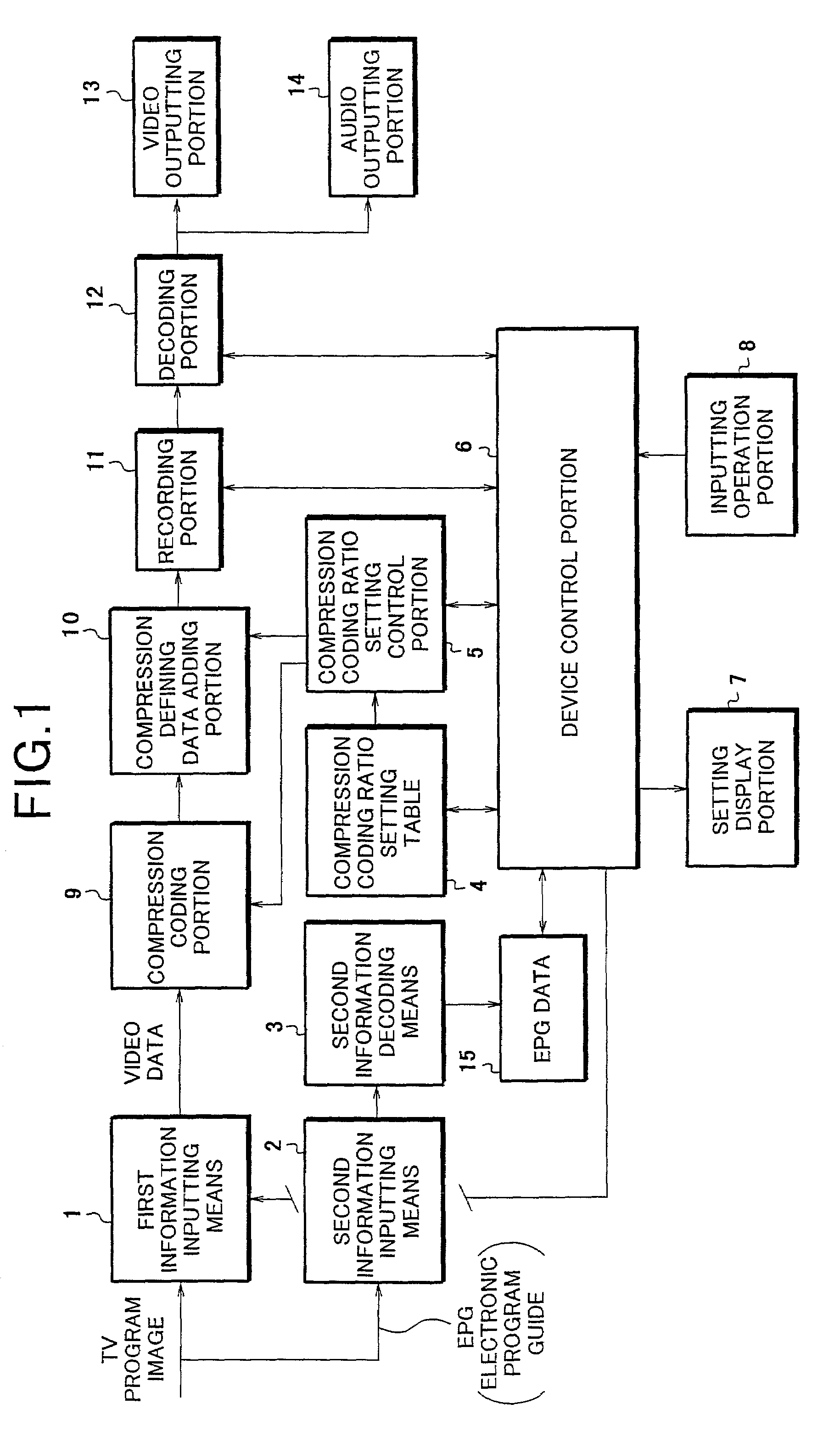
[0035]FIG. 1 is a construction block diagram of an information compressing and recording device according to an embodiment of the present invention.

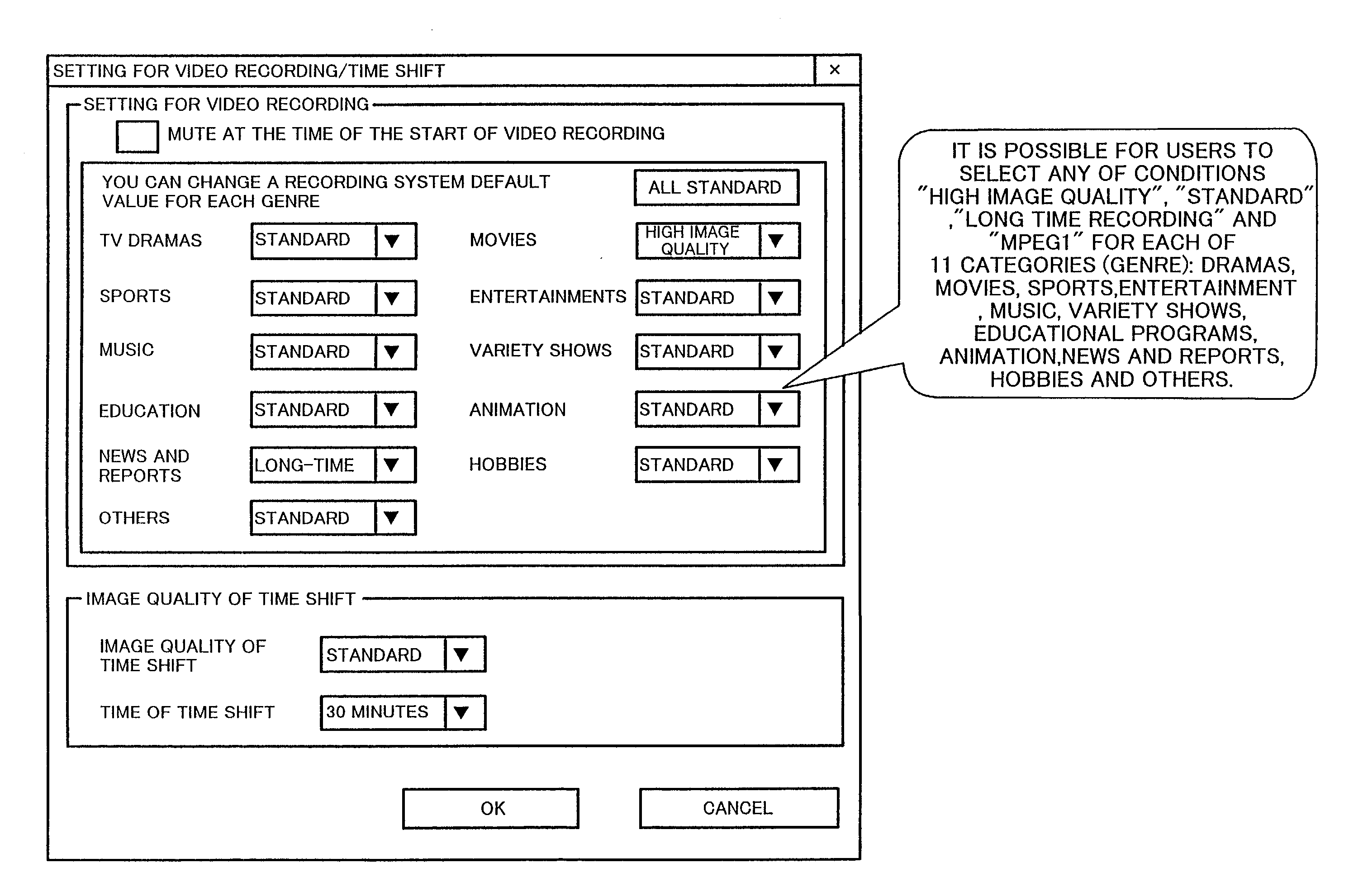
[0036]In FIG. 1, an input television image selected by specifying a TV channel by a first inputting means is input as video data and the video and audio information compressed at a specified compression coding ratio is prepared by a compression coding portion 9. The compressed coded A / V information with a statement of the compressed coding ratio added thereto by a compression definition data adding portion 10 is recorded on a recording portion 11 on the conditions specified by a compression coding ratio control portion 5.

[0037]An electronic program guide (hereinafter referred to as EPG) overlaid on a vertical blanking area of a TV image signal is input to a second information inputting means 2 that in turn a second inf...


PUM


Abstract

When TV images are inputted as video data through a channel selected by the first inputting means, the video information including audio information is compressively encoded at a specified compression coding ratio by a compression coding portion, provided with a compression coding ratio statement attached thereto by the compression definition data adding portion and recorded on a recording portion at the specified compression ratio specified by the compression coding control portion. An electronic program guide overlaid on TV signal, which includes genre information, is input to a second information inputting means, decoded by a second information decoding portion and stored as data. The compression coding ratio is set in a setting table with reference to the data by a compression coding ratio control portion.

Description

BACKGROUND OF THE INVENTION[0001]The present invention relates to a information recording device for recording video data compressed by using a high-efficiently encoding technique such as the video compression method according to MPEG (Moving Picture Experts Group) standard related to motion video. More specifically, this invention relates to data recording devices and video recording / reproducing devices, which can record video data at an optimal compression coding ratio on a recording area of a recording portion, allowing users to freely set a video data compression coding ratio in video recording operation without considering the quality of finally recorded images.[0002]Conventional video recording devices, which can change a data compression coding ratio by using the MPEG algorithm, allow users to select any data compression coding ratio so that the recorded images may have a desirable quality and the data may be reduced to a desirable extent. However, these two parameters “desir...

Claims


Application Information

Patent Timeline
Patent Type & Authority Patents(United States)
IPC IPC(8): H04N7/025H04N5/445H04N7/26H04N5/91H04N5/765H04N5/44H04N5/76H04N5/781H04N5/782H04N5/92H04N7/03H04N7/035H04N7/088H04N7/50H04N9/79H04N9/804H04N9/82H04N19/00H04N19/13H04N19/157H04N19/169H04N19/189H04N19/46H04N19/70
CPCH04N5/782H04N19/42H04N9/7921H04N21/4312H04N21/4314H04N21/4334H04N21/4345H04N21/435H04N21/440254H04N21/440281H04N21/44222H04N21/84H04N19/172H04N19/46H04N19/115H04N19/61H04N19/136H04N19/152H04N19/162H04N19/177H04N7/0884H04N9/8042H04N9/8205
Inventor MORISHITA, TAICHIROSHIGEMORI, TAKESHISENOO, SEIICHI
Owner SHARP KK
Why Eureka
Try Eureka