Electrically actuated brake booster

a brake booster and electric actuator technology, applied in the field of boosters, can solve the problems of increasing costs, increasing costs, and increasing the difficulty of mounting the vacuum brake booster in the vehicle, and achieve the effect of increasing or decreasing the boost ratio

Active Publication Date: 2008-05-06
HITACHI ASTEMO LTD
View PDF8 Cites 45 Cited by
  • Summary
  • Abstract
  • Description
  • Claims
  • Application Information

AI Technical Summary

Benefits of technology

[0014]The electrically actuated brake booster of the present invention includes an urging means that is disposed between the first member or the shaft member and the second member or the tubular member. Therefore, by adjusting the amount of relative displacement between the first member or the shaft member and the second member or the tubular member to an appropriate value, a boost ratio can be increased or decreased. As a result, when the electric actuator is operated as a boost source, a desired boost ratio for the input thrust can be obtained to ensure a desired operability of a brake pedal.

Problems solved by technology

Use of such measures, however, makes it more difficult to mount the vacuum brake booster in a vehicle, and increases costs.
As a result, a boost ratio for the input thrust fails to increase.

Method used


Image

  • Electrically actuated brake booster
  • Electrically actuated brake booster
  • Electrically actuated brake booster

Examples


first embodiment

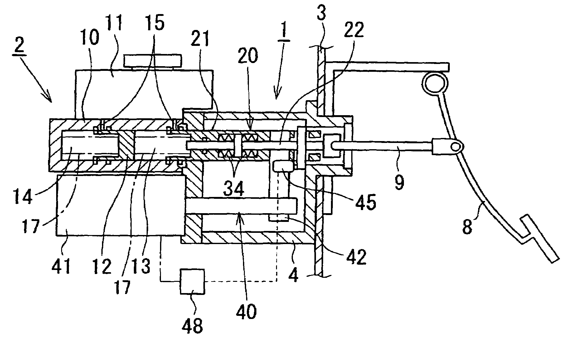
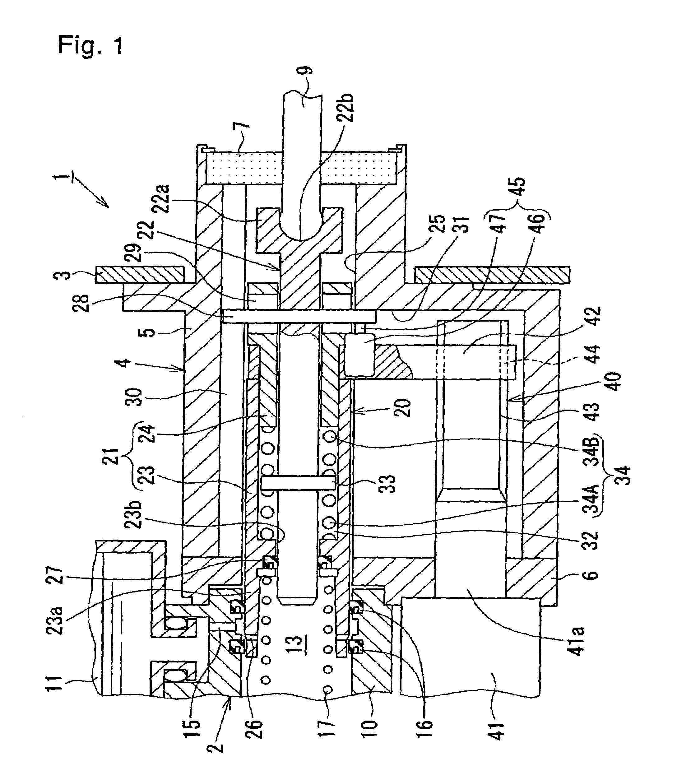
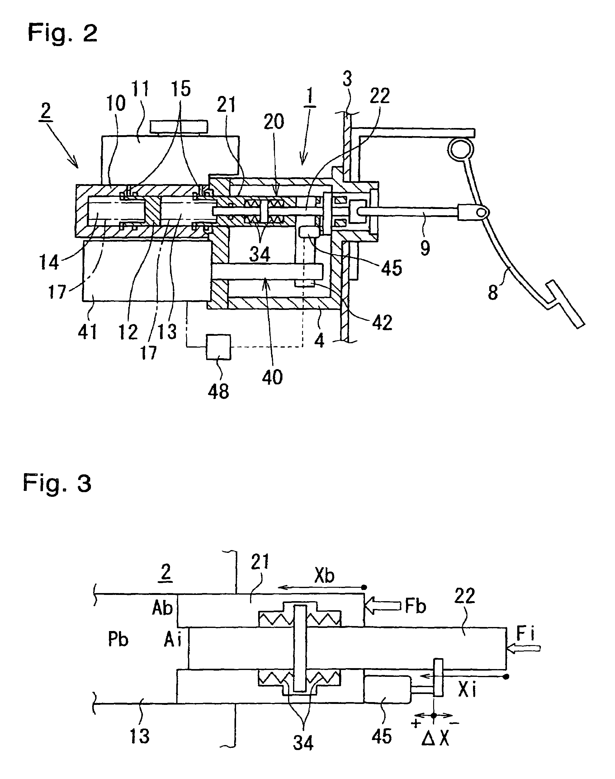
[0026]FIGS. 1 and 2 show an electrically actuated brake booster according to the present invention. The electrically actuated brake booster 1 comprises: a piston assembly 20 (described later) used as a primary piston of a tandem master cylinder 2 and; an electric actuator 40 (also described later) for applying a thrust (a booster thrust) to a booster piston 21 (a tubular member or a second member) which is a constituent component of the piston assembly 20, the piston assembly 20 and the electric actuator 40 being disposed inside and outside a housing 4 (a support member) that is secured to a wall 3 of a vehicle compartment. The housing 4, as best shown in FIG. 1, comprises: a housing body 5, a rear portion of which is inserted into the vehicle compartment; and a covering plate 6 for covering a front opening of the housing body 5. The tandem master cylinder 2 and an electric motor 41, which is a constituent component of the electric actuator 40, are provided on a front surface of the...

second embodiment

[0054]In the second embodiment, a potentiometer 82 (first absolute-displacement detecting means) for detecting an absolute displacement of the input piston 59 relative to a vehicle body is disposed in the attachment member 56, which is secured to the wall 54 of the vehicle compartment. The potentiometer 82 comprises: a body portion 83 containing a resistive element; and a sensor rod 84 extending in parallel with the input piston 59 from the body portion 83 into the vehicle compartment. The sensor rod 84 is constantly urged in its projecting direction by a spring provided in the body portion 83, such that a tip of the sensor rod 84 abuts against a bracket 85 fixed to the rear portion of the input piston 59. On the other hand, the electric motor 66, which is a DC brushless motor, contains a resolver 86 for detecting a magnetic pole position in order to control rotation of the electric motor 66. Besides detecting a rotational displacement of the motor, the resolver 86 functions as rota...


PUM


Abstract

An electrically actuated brake booster capable of obtaining a desired boost ratio for a given input pressure when an electric actuator is activated as a boost source, so as to ensure a desired operability of a brake pedal. The electrically actuated brake booster comprises: an input piston 22 to which an input thrust is applied through an input rod 9 that moves in coordination with operation of a brake pedal 8; and a booster piston 21 to which a booster thrust is applied by an electric actuator 40 that uses an electric motor 41 as a drive source, such that the input piston 22 and the booster piston 21 are disposed to be movable relative to each other but are normally maintained in a neutral position of relative displacement by means of springs 34. While an amount of relative displacement between the pistons 21 and 22 is determined by the potentiometer 45, the electric motor 41 is controlled to adjust the amount of relative displacement to a predetermined value. At the same time, a reaction force acting on the input piston 22 resulting from a hydraulic brake pressure is offset by urging forces of the springs 34 to thereby obtain a desired level of boost ratio.

Description

BACKGROUND OF THE INVENTION[0001]1. Technical Field[0002]The present invention relates to a booster for use in a brake mechanism of an automobile, in particular, an electric booster that utilizes an electric actuator as a boost source.[0003]2. Prior Art[0004]Conventionally, vacuum brake boosters are commonly used in automobile brake mechanisms. Such vacuum brake boosters utilize a negative pressure in an engine intake pipe to boost an input to generate an increased output. In recent years, however, with the development of engines having an improved fuel efficiency, cleaner exhaust gas, and so on, intake pipes have tended to be designed so as to have a relatively low negative pressure. In order to ensure a desired boosting performance or responsiveness of such a vacuum brake booster, a measure must be taken, for example, to increase a size of the vacuum brake booster, to increase a negative pressure by using an ejector, or to provide the vacuum brake booster with an engine-driven vac...

Claims


Application Information

Patent Timeline
Patent Type & Authority Patents(United States)
IPC IPC(8): B60T13/74F16D65/14
CPCB60T13/746
Inventor IKEDA, JUNICHIOHTANI, YUKIO
Owner HITACHI ASTEMO LTD
Why Eureka
Try Eureka