Sequential control circuit
a control circuit and circuit technology, applied in the direction of power supply for data processing, instruments, measurement devices, etc., can solve the problems of inability to change, ic chip glitch or error,
- Summary
- Abstract
- Description
- Claims
- Application Information
AI Technical Summary
Benefits of technology
Problems solved by technology
Method used
Image


Examples
Embodiment Construction
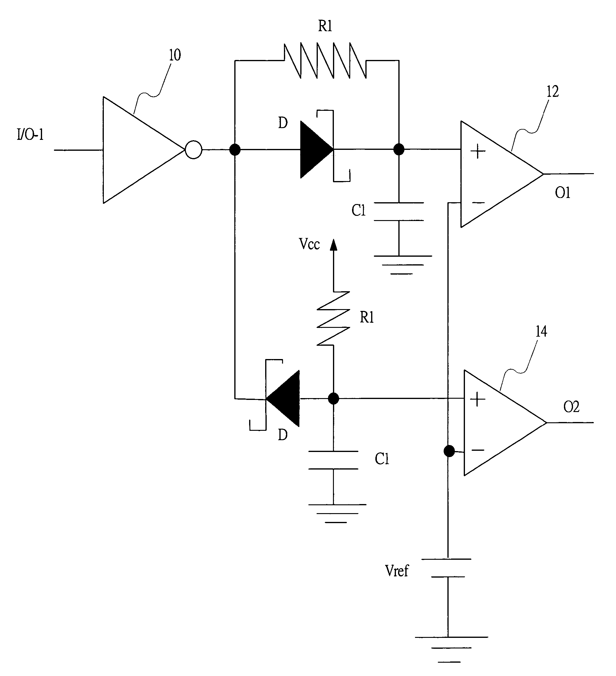
[0017]FIG. 2 is a schematic illustration showing a sequential control circuit of the invention. As shown in FIG. 2, an input terminal of an inverter 10 is connected to an input / output port (I / O-1), and a resistor R1 is connected between an output terminal of the inverter 10 and a first node, which is a positive terminal of a first comparator 12. A Schottky diode D has an anode connected to the output terminal of the inverter 10 and a cathode connected to the first node. A condenser C1 is connected between the first node and a ground. A negative terminal of the first comparator 12 is connected to a reference voltage (Vref). Another resistor R1 is connected between a voltage source (Vcc) and a second node, which is a positive terminal of a second comparator 14. Another Schottky diode D has a cathode connected to the output terminal of the inverter 10 and an anode connected to the second node. Another condenser C1 is connected between the second node and the ground. The negative termin...
PUM
 Abstract
Description
Claims
Application Information