
Systems and methods for measuring sample surface flatness of continuously moving samples

a continuous moving sample and surface flatness technology, applied in the field of continuous moving sample surface flatness measurement systems, can solve the problems of frequent warpage, limited usefulness of shadow moiré for routine automated analysis, and high cost of motion system, so as to achieve efficient and cost-effective measurement and quantification of surface flatness

Active Publication Date: 2008-05-06
AKROMETRIX LLC
View PDF28 Cites 11 Cited by
  • Summary
  • Abstract
  • Description
  • Claims
  • Application Information

AI Technical Summary

Benefits of technology

Enables efficient and cost-effective measurement of surface flatness for continuously moving samples, reducing production line disruptions and improving product quality by eliminating the need for expensive motion systems and allowing real-time monitoring.

Problems solved by technology

Non-flatness, or warpage, is a frequent problem in manufacturing, due to inadequacies in design, materials, and / or processing of components.
Without phase stepping or some equivalent technique, shadow moiré is of limited usefulness for routine automated analysis.
The motion system is typically expensive, especially if the sample and / or the grating is large or heavy.
If these conditions are not met, errors are introduced into the analysis.
These precision requirements for the motion system generally make the analysis slow and expensive.
For example, where materials, such as paper, are formed, woven, or extruded on a continuous basis, production flows cannot be stopped to measure samples of the materials without inducing flaws into the materials.
In addition, some samples cannot readily be stopped and started because of sample characteristics, such as high weight, and / or the requirements of the remainder of the production line.
Because the above-described techniques require a stationary support structure to hold the sample in place during data acquisition and / or grating / sample translation, they cannot readily be applied to measure surface flatness of continuously moving samples.

Method used


Image

  • Systems and methods for measuring sample surface flatness of continuously moving samples
  • Systems and methods for measuring sample surface flatness of continuously moving samples
  • Systems and methods for measuring sample surface flatness of continuously moving samples

Examples


Embodiment Construction

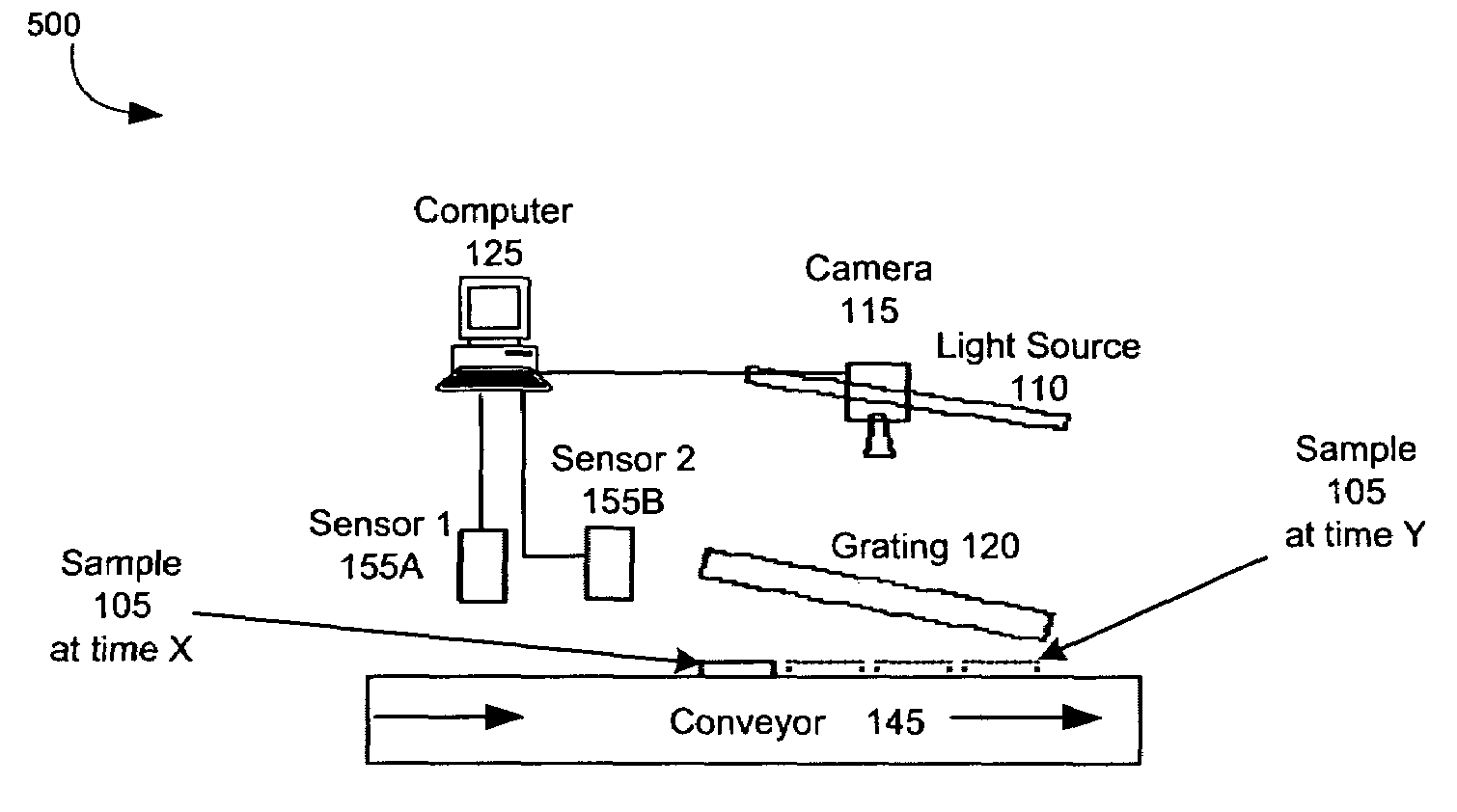
[0035]The invention is directed to systems and methods for measuring sample surface flatness of continuously moving samples. Efficient and cost-effective measurement of sample surface flatness on a production line can help manufacturers in a variety of industries to maximize product quality and reduce costs. It can also help manufacturers to readily recognize processing deficiencies. The manufacturers can be in the electronics, metal fabrication, paper, textile, and / or polymer film industries, for example.

[0036]In accordance with an exemplary embodiment of the invention, a conveyor continuously conveys a sample beneath a grating disposed at a non-zero angle with respect to the plane of conveyance. As used herein, the term “sample” refers to an object or a portion of an object for which a surface flatness measurement is desired. The sample can comprise, for example, a mechanical component, such as a printed circuit board, a sheet material, such as paper, or a portion thereof. Due to ...


PUM


Abstract

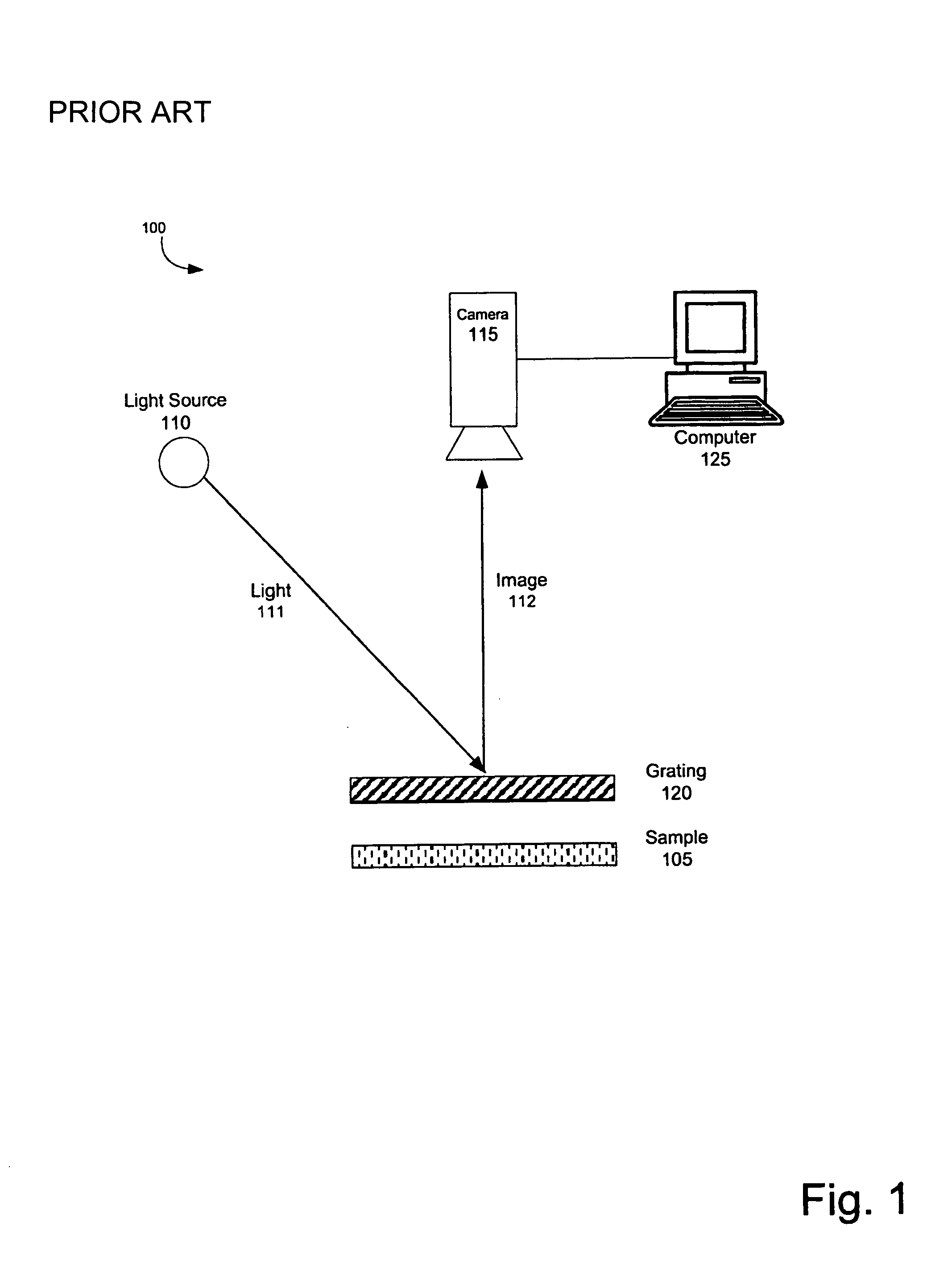
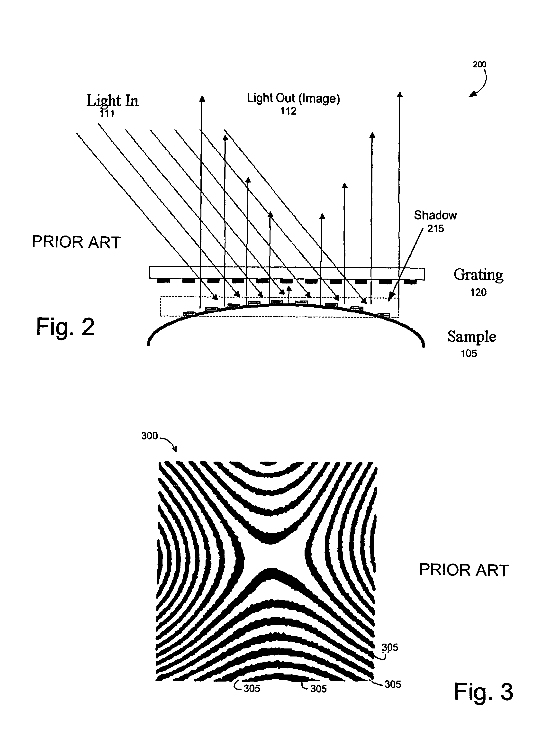
Measurement of sample surface flatness of a continuously moving sample. A conveyor continuously conveys a sample beneath a grating disposed at a non-zero angle with respect to the plane of conveyance. The relative distance between the sample and the angled grating changes with the horizontal translation of the sample. A camera disposed above the sample and the grating captures, at constant time intervals, a sequence of images, each image comprising a shadow moiré fringe pattern that is indicative of the sample's surface flatness. The continuous change in relative distance between the sample and the grating introduces a known or unknown phase step between the shadow moiré fringe patterns of each successive image. A computer associated with the camera processes the images to determine phase values of pixels at, and the relative height of the sample surface at, selected pixel locations of the sample.

Description

RELATED PATENT APPLICATION[0001]The present patent application claims priority under 35 U.S.C. § 119 to U.S. Provisional Patent Application No. 60 / 617,843, entitled “Machine for Measuring Sample Surface Flatness of Continuously Moving Parts or Sheet Material,” filed Oct. 13, 2004, which is hereby incorporated by reference.FIELD OF THE INVENTION[0002]The invention relates generally to measuring sample surface flatness of objects, and more particularly to quantifying the surface flatness of continuously moving samples using a shadow moiré image processing technique and phase-sensitive analysis.BACKGROUND OF THE INVENTION[0003]Surface flatness is a common measurement specification over a wide range of manufacturing industries. Flatness critically affects, for example, the reliability and assembly yield of electronic products, the cosmetic appearance and handling characteristics of paper products, and the mechanical fit and functionality of fabricated metal components. Non-flatness, or ...

Claims


Application Information

Patent Timeline
Patent Type & Authority Patents(United States)
IPC IPC(8): G01B9/02G01B11/30G01D5/36G06K9/00
CPCG01B11/254G01B11/306G06T7/0057G06T7/521
Inventor ZWEMER, DIRK ADRIANPAN, JIAHUIPETRICCIONE, GREGORY JAMESMCCARRON, SEAN PATRICK
Owner AKROMETRIX LLC
Learn More