
Method and apparatus for locking a table in a network switch

a network switch and address table technology, applied in the field of communication systems, can solve problems such as additional conflicts, errors, and further complicated situations, and achieve the effect of reducing the amount and complexity of logi

Inactive Publication Date: 2008-05-06
GLOBALFOUNDRIES INC
View PDF20 Cites 5 Cited by
  • Summary
  • Abstract
  • Description
  • Claims
  • Application Information

AI Technical Summary

Benefits of technology

[0010]There exists a need for an arrangement capable of providing controlled access to an address table without the use of arbitration logic. There is also a need for an arrangement that minimizes the amount and complexity of the logic that resides on-chip within a network switch.
[0012]In accordance with one aspect of the present invention, a method of locking an address table within a network switch comprises the steps: allocating prescribed time slots for accessing the address table to various components of the multiport switch; determining, during a time slot allocated to a designated component, if any of the other components are currently transacting with the address table; locking out the designated component from accessing the address table, if one of the other components is currently transacting with the address table; and allowing the designated component access to the address table if none of the other components are currently transacting with the address table. The present method improves access to the address table while minimizing the amount of logic normally required to reduce potential conflicts. This is accomplished by designating prescribed time slots during which various components of the network switch may access the address table. Each component of the network switch must then determine, during its assigned time slot, if other components are accessing the address table prior to conducting a transaction.
[0013]In accordance with another aspect of the present invention, an arrangement is provided for controlling access to information stored in a network switch. The arrangement includes an address table, a plurality of components, and a scheduler. The address table stores entries that contain addresses of network stations connected to the network switch, and allows access to the entries by the plurality of components. The scheduler allocates prescribed time slots to each component for accessing the address table. Each component is configured to determine if any other components are currently transacting with the address table during its allocated time slot. If none of the other components are currently transacting with address table, then the component assigned the current time slot will proceed to access the address table. According to the present arrangement, access to the address table is improved, while minimizing the amount of logic normally required to reduce potential conflicts.

Problems solved by technology

Furthermore, additional conflicts may result if, for example, the first component attempts to modify an entry in the address table before the second component completes its modifications to the same entry.
This situation is further complicated when the network switch incorporates an address table that contains multiple addresses per entry.
Additionally, errors may occur if both the first component and the second component attempt to access the same address within the entry.
Rather, each component must request access to the address table through the arbitration logic, hence reducing the possibility of multiple access to the same entry.
The aforementioned arrangement has a disadvantage of requiring additional logic to receive requests, perform arbitration, and grant access to the address table.
This is particularly problematic in systems wherein the network switch is embodied on a single chip.
Accordingly, one problem associated with network switches is the potential for conflicts resulting from multiple components attempting to simultaneously access the address table.
Another problem associated with network switches is the amount and complexity of the logic normally incorporated on the chip in order to reduce such potential conflicts.

Method used


Image

  • Method and apparatus for locking a table in a network switch
  • Method and apparatus for locking a table in a network switch
  • Method and apparatus for locking a table in a network switch

Examples


Embodiment Construction

[0026]The present invention will be described with the example of a switch in a packet switched network, such as an Ethernet (IEEE 802.3) network. It will become apparent, however, that the present invention is also applicable to other packet switched systems, as described in detail below, as well as to other types of systems in general.

Switch Architecture Overview

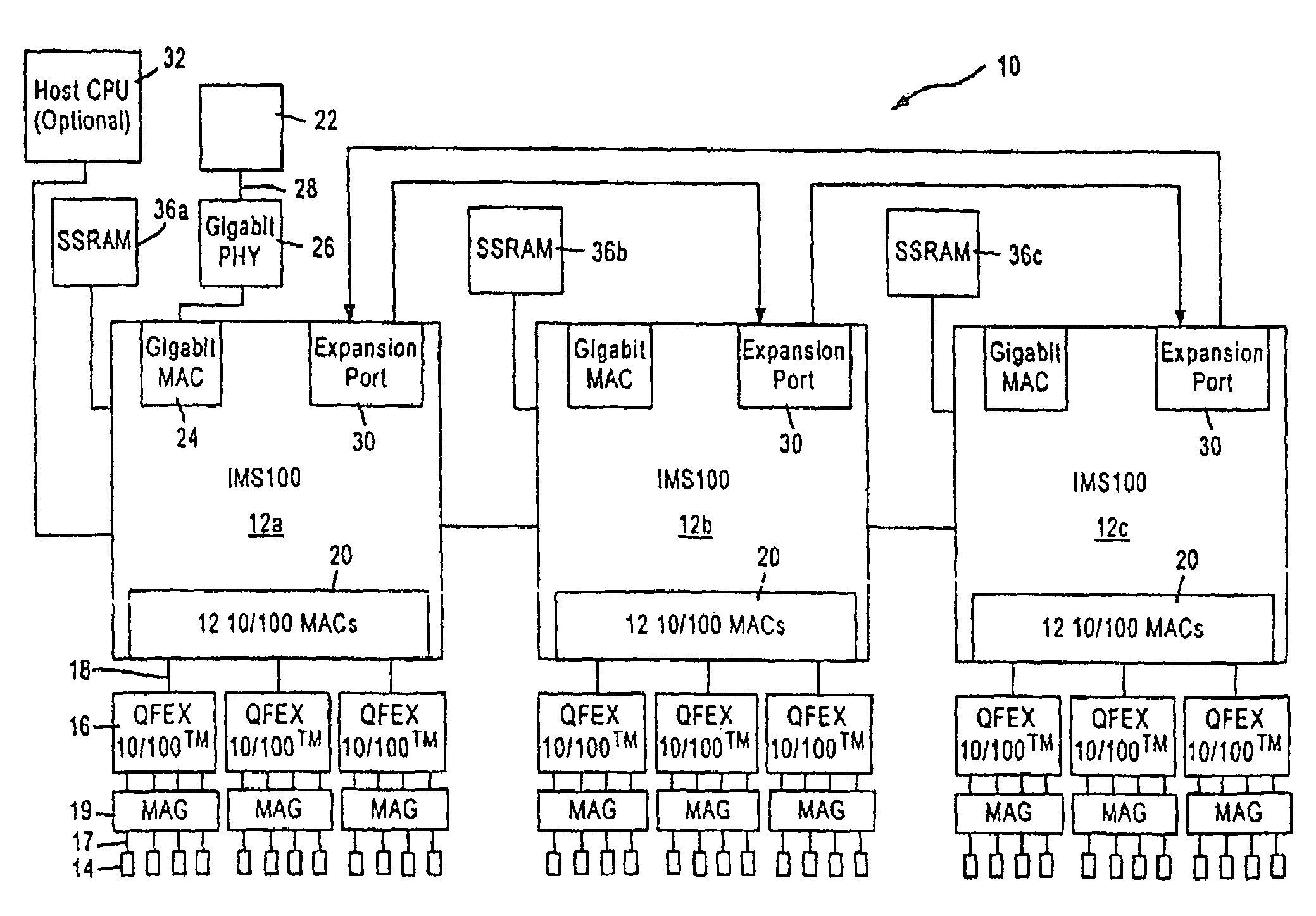
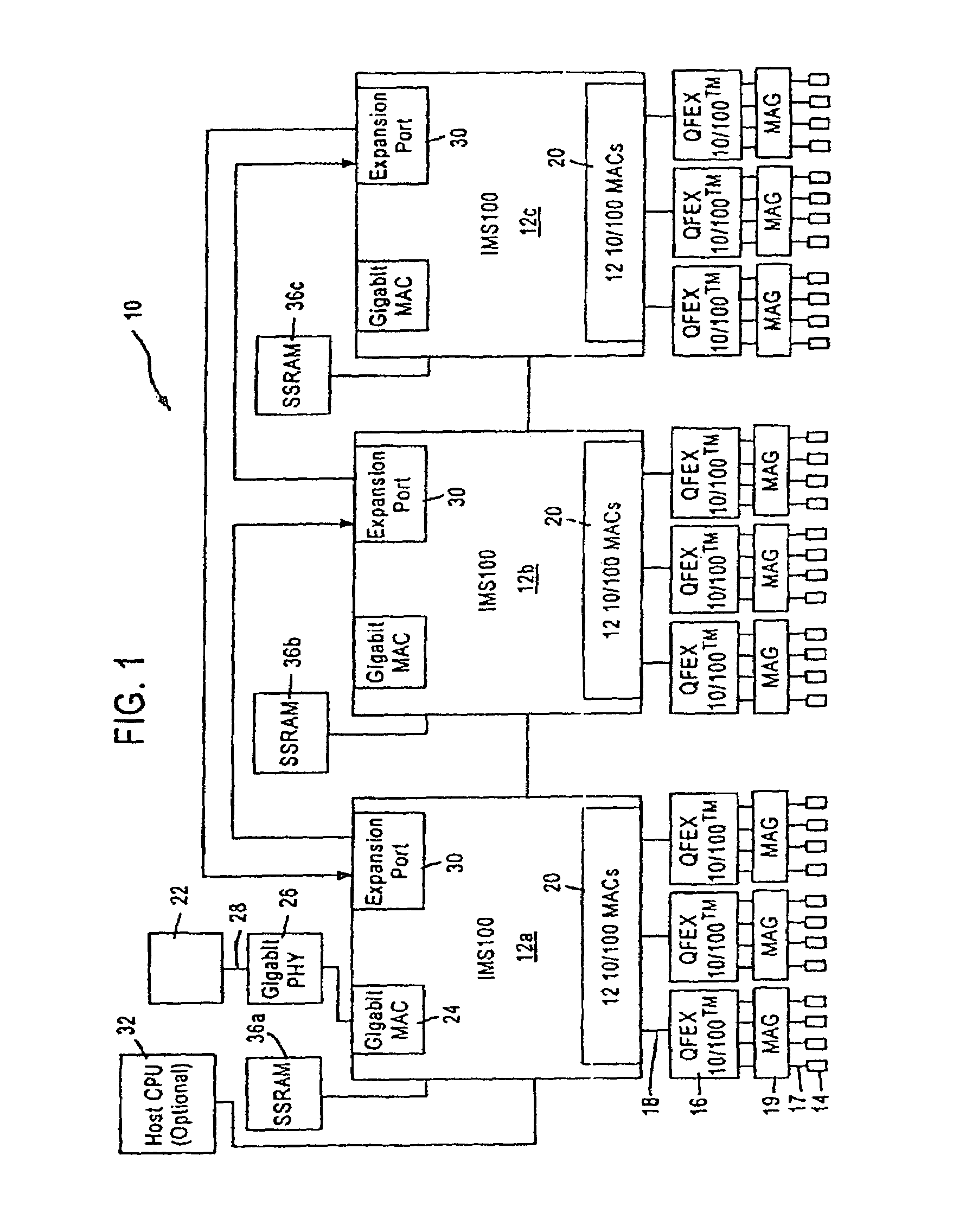
[0027]FIG. 1 is a block diagram of an exemplary system in which the present invention may be advantageously employed. The exemplary system 10 is a packet switched network, such as an Ethernet (IEEE 802.3) network. The packet switched network includes integrated multiport switches (IMS) 12 that enable communication of data packets between network stations. The network may include network stations having different configurations, for example twelve (12) 10 megabit per second (Mb / s) or 100 Mb / s network stations 14 (hereinafter 10 / 100 Mb / s) that send and receive data at a network data rate of 10 Mb / s or 100 Mb / s, and a 1000 Mb...


PUM


Abstract

An apparatus and method are disclosed for locking a table within a network switch. The table is used to store entries that contain addresses of network stations connected to the network switch. A scheduler regulates access to the address table by allocating prescribed time slots during which components of the network switch can access the address table. Each component requiring access to the address table must wait until it is assigned a time slot in order to further determine if any other components are accessing the address table. If none of the other components are accessing the address table, then the component requiring access can initiate a transaction.

Description

RELATED APPLICATION[0001]This application is a continuation of and contains subject matter related to the subject matter disclosed in U.S. patent application Ser. No. 09 / 296,558, filed on Apr. 22, 1999 now abandoned.FIELD OF THE INVENTION[0002]The present invention relates to communication systems, and more particularly, to a method and apparatus for controlling access to an address table in a network switch.DESCRIPTION OF THE RELATED ART[0003]Modern communication systems, such as computer networking systems or communication networks, provide constant transmission of data between end stations and / or intermediate stations such as routers and signal amplifiers. Computer networking systems, such as packet switched networks (e.g., Ethernet networks), often require transmission of data to a single end station or to multiple end stations within the network. The data originates from a user program, and is segmented into multiple data frames and subsequently transmitted in order to simplify...

Claims


Application Information

Patent Timeline
Patent Type & Authority Patents(United States)
IPC IPC(8): H04L12/54G06F13/00G06F15/173
CPCH04L49/90H04L49/901
Inventor CHIANG, JOHN
Owner GLOBALFOUNDRIES INC
Learn More