Electromagnetic flowmeter

a flowmeter and electromagnet technology, applied in the direction of volume flow measurement devices, liquid/fluent solid measurement, instruments, etc., can solve the problems of error in flow rate measurement, flow rate error, and flow rate error to be obtained, so as to accurately detect the flow rate of fluid. accurate measurement

Inactive Publication Date: 2008-05-06
YAMATAKE HONEYWELL CO LTD
View PDF22 Cites 24 Cited by
  • Summary
  • Abstract
  • Description
  • Claims
  • Application Information

AI Technical Summary

Benefits of technology

[0052]The present invention has been made to solve the above problems, and has as its object to provide an electromagnetic flowmeter which can accurately measure the flow rate of a fluid by accurately detecting a state in which the ratio of variation components dependent on a characteristic or state of a fluid and a state in a measuring tube is not constant between a v×B component dependent on the flow velocity of the fluid and a ∂A / ∂t component independent of the flow velocity of the fluid or a state in which the characteristic or state of the fluid or the state in the measuring tube varies and, correcting the flow rate of the fluid.

Problems solved by technology

If, therefore, the tube is not filled with a fluid or air bubbles are mixed in the fluid, an error occurs in flow rate measurement.
As a consequence, a span variation occurs in an output from the electromagnetic flowmeter, and a flow rate error occurs.
This causes a span variation in an output, resulting in an error in the flow rate to be obtained.
As described above, when a substance other than a fluid to be measured is mixed in the tube, for example, a gas and a liquid or the like constitute a multiphase flow (a fluid level variation can also be regarded as a case wherein air is mixed in the fluid), it is difficult to accurately measure a flow rate by using a general electromagnetic flowmeter.
For this reason, when a signal electromotive force decreases as the flow rate approaches 0, the detected fluid level contains a large error, and the accuracy of sensitivity correction deteriorates, resulting in an flow rate measurement error.
Consequently, as the required flow rate measurement accuracy increases, a flow rate measurement error occurs in the electromagnetic flowmeter in reference 3.
This flow rate measurement error becomes conspicuous in particular when measurement is performed by using high-frequency excitation with an exciting current having a high frequency or when a fluid with a low conductivity is measured.
Even in this case, if the volume (sectional area) of the fluid varies, an error occurs in the flow rate.
This may make impossible to accurately measure a flow rate even by applying the principle of reference 3.

Method used


Image

  • Electromagnetic flowmeter
  • Electromagnetic flowmeter
  • Electromagnetic flowmeter

Examples


first embodiment

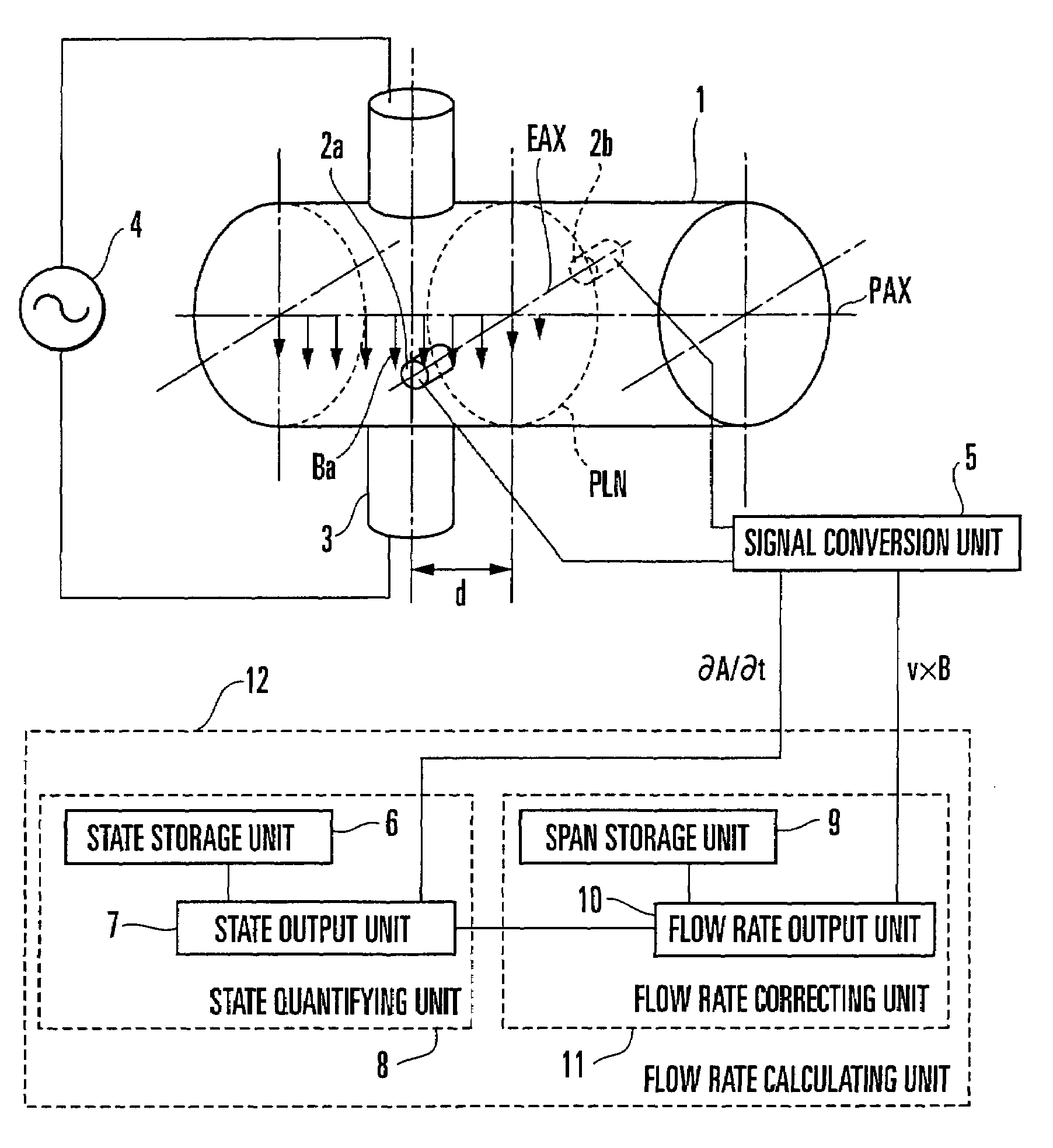
[0258]The first embodiment of the present invention will be described in detail next. This embodiment uses the first arrangement described above. An electromagnetic flowmeter according to this embodiment includes one exciting coil and a pair of electrodes, and has the same arrangement as that of the electromagnetic flowmeter shown in FIG. 36 except for the signal processing system. The principle of this embodiment will therefore be described by using reference numerals in FIG. 36. This embodiment uses the first extraction method as a method of extracting a ∂A / ∂t component from a resultant vector, and the first correction method as a flow rate correction method.

[0259]When an exciting current with an angular frequency ω0 is supplied to an exciting coil 3, and a parameter h1 is provided, an inter-electrode electromotive force E110 is represented by the following equation according to equations (35), (93), and (99).

[0260]E⁢⁢110=rkg⁡[h⁢⁢1]·ω⁢⁢0·b⁢⁢1·exp⁢{j·(π / 2+θ⁢⁢1+θ⁢⁢g⁡[h⁢⁢1])}+rkf⁡[h⁢...

second embodiment

[0302]The second embodiment of the present invention will be described next. This embodiment uses the first arrangement like the first embodiment. The second embodiment uses the first extraction method as a method of extracting a ∂A / ∂t component from a resultant vector, and the second correction method as a flow rate correction method. Since the principle of this embodiment is the same as that of the first embodiment up to the point where the parameter h1 is obtained, only the difference after the parameter h1 is obtained will be described.

[0303]A normalized electromotive force EvBn1 obtained by normalizing an electromotive force EvB1 of a v×B component with an electromotive force difference EdA1 and multiplying the resultant value by ω0 is represented by the following equation by referring to equation (100).

[0304]EvBn⁢⁢1=⁢EvB⁢⁢1 / EdA⁢⁢1·ω⁢⁢0=⁢(rkf⁡[h⁢⁢1] / rkg⁡[h⁢⁢1])·V·⁢exp⁢{j·(θ⁢⁢f⁡[h⁢⁢1]-θ⁢⁢g⁡[h⁢⁢1]-π / 2)}(135)

[0305]The reason why the result obtained by normalizing the electromotive...

third embodiment

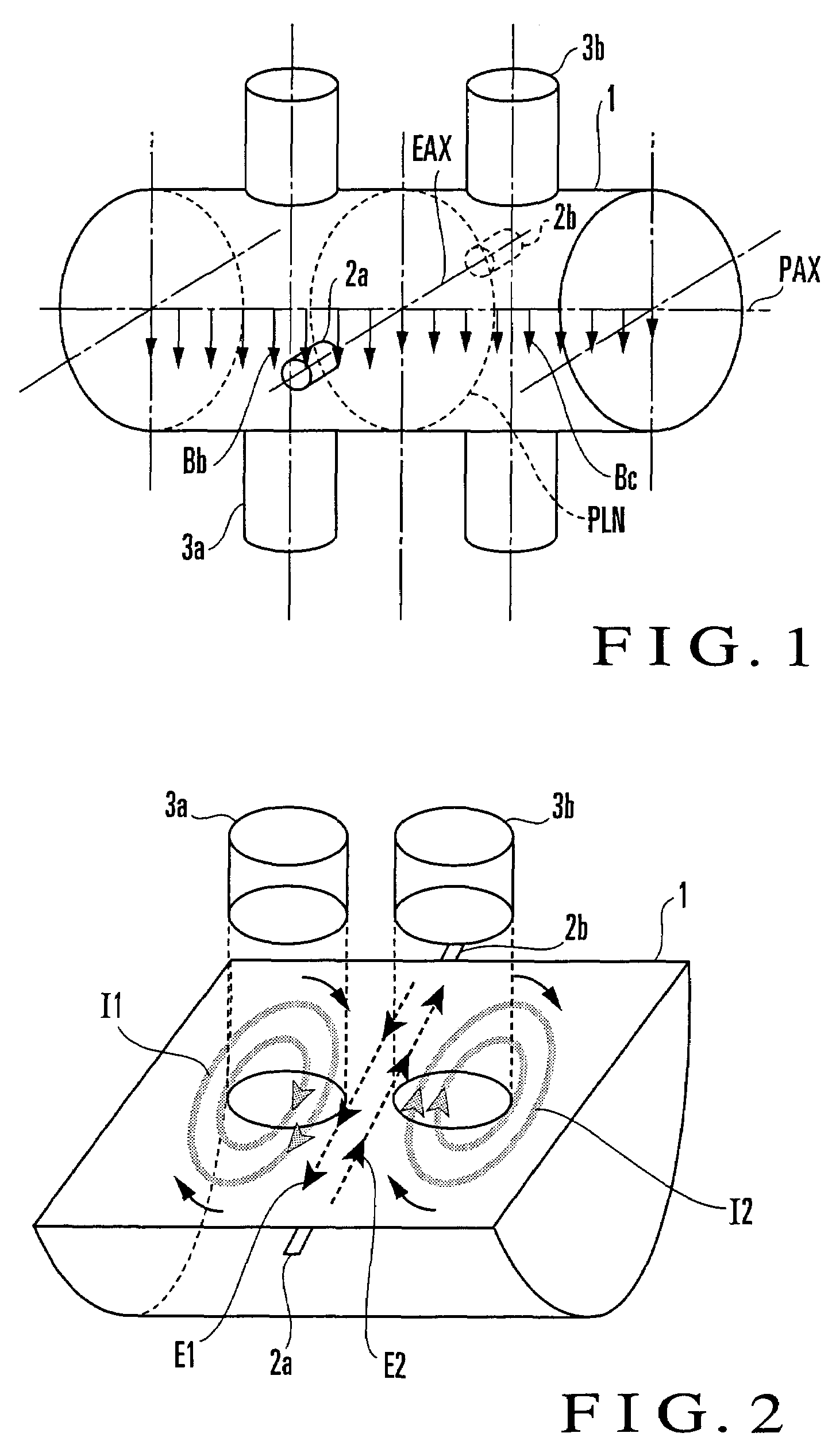
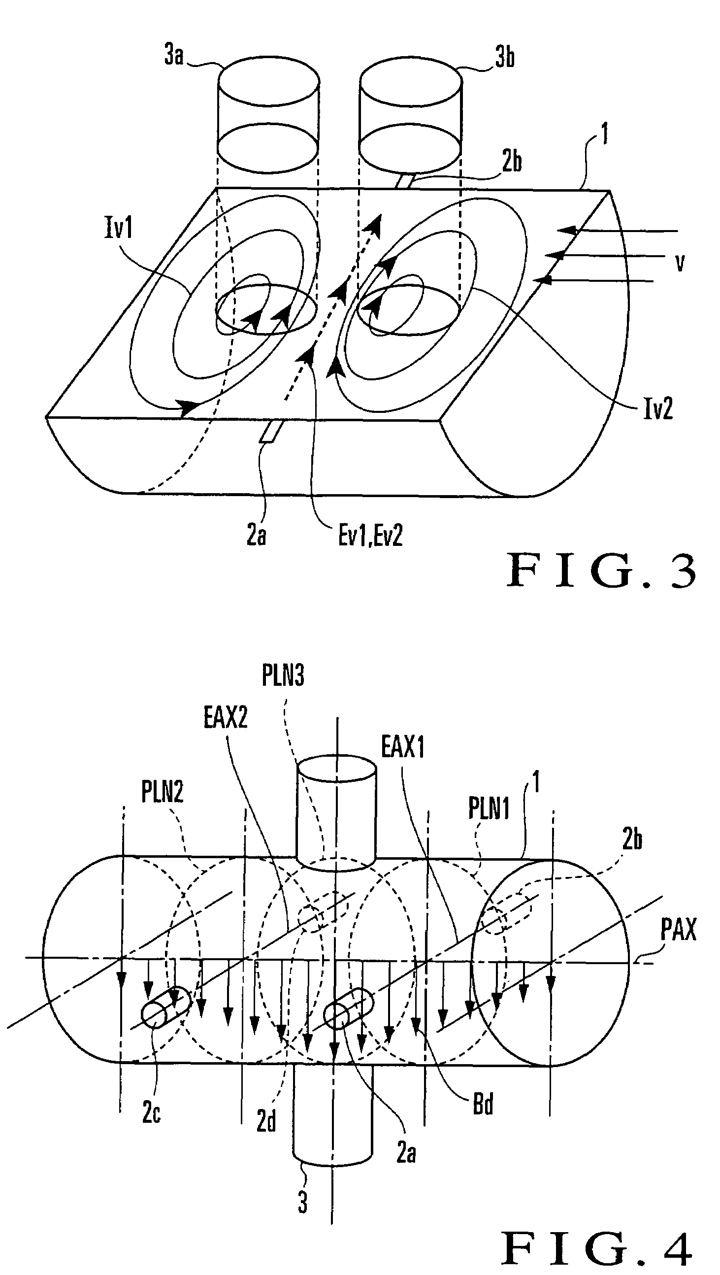
[0321]The third embodiment of the present invention will be described next. This embodiment uses the second arrangement described above. An electromagnetic flowmeter according to this embodiment includes two exciting coils and a pair of electrodes, and has the same arrangement as that of the electromagnetic flowmeter shown in FIG. 1 except for the signal processing system. The principle of this embodiment will therefore be described by using reference numerals in FIG. 1. This embodiment uses the first extraction method as a method of extracting a ∂A / ∂t component from a resultant vector, and the first correction method as a flow rate correction method.

[0322]Assume that the first exciting current having an angular frequency ω0 is supplied to a first exciting coil 3a, the second exciting current having the angular frequency ω0 with a phase difference Δθ2 with respect to the first exciting current is supplied to a second exciting coil 3b (i.e., an excitation state ST1), and a parameter ...


PUM


Abstract

An electromagnetic flowmeter includes a measuring tube, an electrode, an exciting unit, a signal conversion unit, and a flow rate calculating unit. The signal conversion unit extracts a ∂A / ∂t component irrelevant to a flow velocity of the fluid and a v×B component originating from the flow velocity of the fluid from a resultant electromotive force of an electromotive force ∂A / ∂t, with A, t, v, and B respectively representing a vector potential, a time, a flow velocity, and a magnetic flux density. The flow rate calculating unit extracts a variation component dependent on a parameter from the ∂A / ∂t component, corrects a span which is a coefficient applied to a magnitude V of the flow velocity of the v×B component, and calculates the flow rate of the fluid from the v×B component whose span is corrected.

Description

BACKGROUND OF THE INVENTION[0001]The present invention relates to an electromagnetic flowmeter and, more particularly, to an electromagnetic flowmeter which detects a characteristic or state of a fluid or a state in a measuring tube and corrects the flow rate of the fluid.[0002]An electromagnetic flowmeter is a flowmeter which can measure a flow rate with stability owing to its characteristics, and has established a position as a high-accuracy flowmeter. However, a conventional electromagnetic flowmeter is assumed to operate under a condition where the tube is filled with a fluid to be measured, and is generally designed to obtain the flow rate of the fluid by detecting a signal proportional to the flow velocity of the fluid and multiplying the flow velocity by the sectional area of the tube. If, therefore, the tube is not filled with a fluid or air bubbles are mixed in the fluid, an error occurs in flow rate measurement.[0003]For example, as the level of a fluid in the tube varies,...

Claims


Application Information

Patent Timeline
Patent Type & Authority Patents(United States)
IPC IPC(8): G01F1/00
CPCG01F1/584G01F1/60
Inventor YAMAMOTO, TOMOSHIGE
Owner YAMATAKE HONEYWELL CO LTD
Why Eureka
Try Eureka