Golf club head having a connecting structure for a high degree of flexibility

a golf club head and connecting structure technology, applied in the field of golf club head connecting structure for high degree of flexibility, can solve the problems of disadvantageous limitation of the striking plate portion 20/b> for performing deformation ability, number of design limitations, etc., and achieve the effect of enhancing the elastic deformation of the rear connecting wall and high degree of flexibility

Inactive Publication Date: 2008-05-13
FUSHENG PRECISION
View PDF32 Cites 42 Cited by
  • Summary
  • Abstract
  • Description
  • Claims
  • Application Information

AI Technical Summary

Benefits of technology

[0009]The primary objective of this invention is to provide a golf club head having a connecting structure for a high degree of flexibility, wherein an upstanding bent edge of a rear-connecting wall of a striking plate component connects with a sidewall of a rear-assembling component. Accordingly, the rear-connecting wall of the striking plate component separates a striking face from the rear-assembling component such that a rearward extended length of the rear-connecting wall is enlarged and elastic deformation of the rear-connecting wall is enhanced.
[0010]The secondary objective of this invention is to provide the golf club head having a rear-assembling flange of the rear-assembling component to connect with the upstanding bent edge of the rear-connecting wall of the striking plate component. Accordingly, the rear-assembling flange of the rear-assembling component further separates the striking face from the rear-assembling component such that a rearward extended length of the rear-connecting wall is enlarged and elastic deformation of the rear-connecting wall is enhanced.
[0011]Another objective of this invention is to provide the golf club head having an inner circumference of the rear-connecting wall of the striking plate component connects with the rear-assembling flange of the rear-assembling component. Accordingly, the rear-assembling flange of the rear-assembling component improves an engagement of the striking plate component with the rear-assembling component such that an assembled reliability is insured.

Problems solved by technology

Disadvantageously, a shorter length of the annular wall 22 of the striking plate portion 20 may cause a low degree of flexibility in elastic deformation.
In other words, an area of the annular wall 22 of the striking plate portion 20 for performing deformation ability is disadvantageously limited.
Such a golf club head structure is widely applied in U.S. Pat. No. 6,099,414, entitled “Golf Club Head and Method for Producing the Same,” U.S. Pat. No. 6,743,120, entitled “Iron Golf Club Head,” and U.S. Publication No. 2004 / 0097301, entitled “Golf Club Head.” As has been discussed above, a number of design limitations, however, exist for the annular wall of the striking plate portion due to difficulties in manufacturing.
Such unwanted design limitations may alleviate the improvement of the striking ability contributed from the annular wall of the striking plate portion.

Method used


Image

  • Golf club head having a connecting structure for a high degree of flexibility
  • Golf club head having a connecting structure for a high degree of flexibility
  • Golf club head having a connecting structure for a high degree of flexibility

Examples


first embodiment

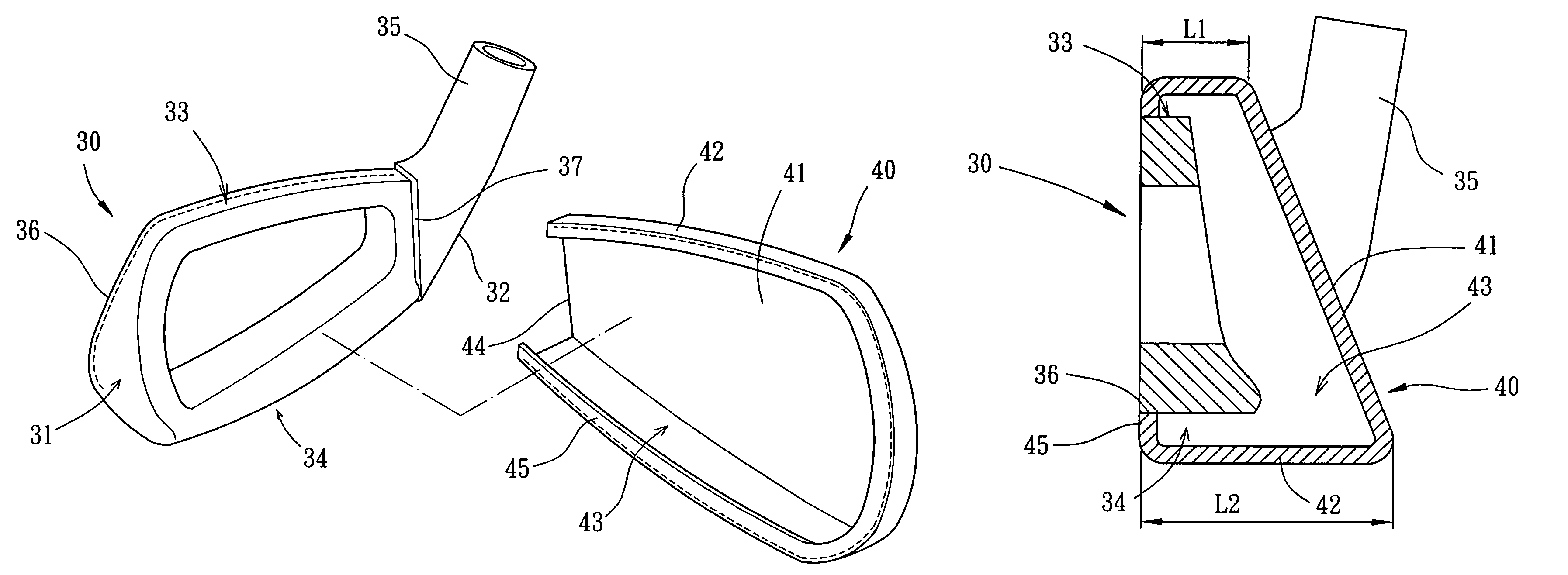
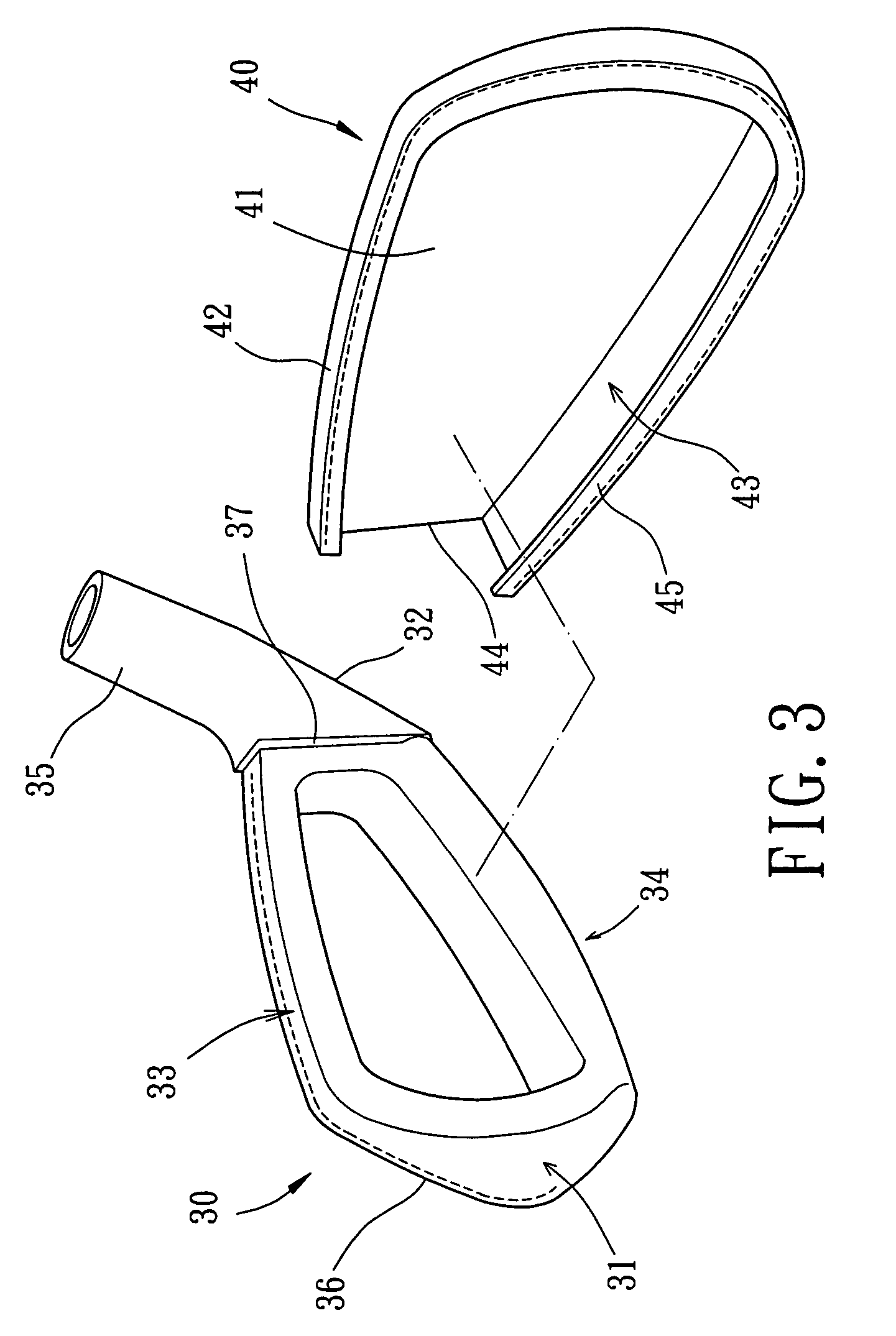
[0031]Turning now to FIGS. 3 and 4, construction of the club head body component 30 shall be described in detail. The club head body component is a monolithic body, and constructed from materials selected from a group consisting of metal, nonmetal and alloy. In particular, the club head body component 30 so constructed from nonmetal can be formed either from similar or dissimilar materials. In the first embodiment, the club head body component 30 includes a toe portion 31, a heel portion 32, a crown portion 33, a sole portion 34, a hosel portion 35, a connecting rear-end portion 36 and a lateral wall portion 37. Each configuration of the toe portion 31, the heel portion 32, the crown portion 33, the sole portion 34 and the hosel portion 35 has an ordinary or common structure of the art. The club head body component 30 further includes an opening (not labeled) which serves to form a club head body. The connecting rear-end portion 36 is successively disposed on peripheries of the crow...

fifth embodiment

[0042]Construction of the weight component 50 shall be described in detail with reference to FIGS. 8 and 9. In the fifth embodiment, the weight component 50 includes a first side portion 51, a second side portion 52, a top portion 53, a bottom portion 54 and a connecting rear-end portion 55. The connecting rear-end portion 55 is successively disposed on peripheries of the top portion 53, the first side portion 51, the bottom portion 54 and the second side portion 52. Typically, lower dimensions of the weight component 50 are designed for being greater than upper dimensions thereof in aiding to lower a center of gravity.

[0043]Construction of the striking plate component 60 shall be described in detail with reference to FIGS. 8 and 9. In the fifth embodiment, the striking plate component 60 is constructed from materials selected from a group consisting of metal, nonmetal and alloy which has relatively low specific gravity. The striking plate component 60 includes a striking face 61, a...


PUM


Abstract

A golf club head includes a striking plate component and a rear-assembling component mechanically connected thereto. The striking plate component provides with a striking face and a rear-connecting wall. The rear-connecting wall is bent rearward and extended a rearward extended length from the striking face. The rear-assembling component provides with a sidewall corresponding to the rear-connecting wall of the striking plate component. In assembling, the rear-connecting wall of the striking plate component connects with the sidewall of the rear-assembling component by means of an upstanding bent edge or a rear-assembling flange such that the rear-connecting wall separates the striking face from the rear-assembling component for permitting elastic deformation.

Description

BACKGROUND OF THE INVENTION[0001]1. Field of the Invention[0002]The present invention relates to a golf club head having a connecting structure for a high degree of flexibility. Particularly, the present invention relates to the golf club head having a rear-connecting wall of a striking plate component to connect with a rear-assembling component. More particularly, the present invention relates to the rear-connecting wall of the striking plate component of the golf club head separating a striking face from the rear-assembling component.[0003]2. Description of the Related Art[0004]A conventional golf club head structure is described in Taiwanese Patent Publication No. 557,806 and corresponding U.S. Pat. No. 6,506,129, entitled “golf club head capable of enlarging flexible area of ball-hitting face thereof.” Referring to FIGS. 1 and 2, the golf club head structure includes a club head body portion 10 and a striking plate portion 20 mechanically connected thereto. The club head body po...

Claims


Application Information

Patent Timeline
Patent Type & Authority Patents(United States)
IPC IPC(8): A63B53/04
CPCA63B53/047A63B53/04A63B53/0466A63B2053/0416A63B2053/0491A63B53/0487A63B60/02A63B53/0416A63B60/00
Inventor CHEN, CHAN-TUNG
Owner FUSHENG PRECISION
Why Eureka
Try Eureka