Belt driven centrifugal separator with multi-stage, belt deterioration alerting display

a technology of centrifugal separator and warning display, which is applied in the direction of centrifuges, dynamo-electric converter control, separation processes, etc., can solve the problems of motor damage, belt or other components of the driving power transmission mechanism would suffer damage, and the vertical dimension of the centrifugal separator increases, so as to accurately detect a wide range of malfunctions

Inactive Publication Date: 2008-05-13
KOKI HLDG CO LTD
View PDF7 Cites 5 Cited by
  • Summary
  • Abstract
  • Description
  • Claims
  • Application Information

AI Technical Summary

Benefits of technology

[0010]In view of the foregoing, it is an object of the invention to provide a centrifugal separator that can accurately detect a broad range of malfunction and alert the user of the present malfunction status.
[0011]Another object of the invention is to provide a centrifugal separator that can prevent the mechanical wear of driving power transmission components, such as belt, from increasing.
[0012]Still another object of the invention is to provide a centrifugal separator that can prevent the motor from being damaged caused by the mechanical wear of the driving power transmission components.

Problems solved by technology

However, the direct driving type centrifugal separator requires a motor to be disposed in alignment with the rotational shaft of the rotor, so that the position in which the motor is disposed is restricted and the vertical dimension of the centrifugal separator increases.
Even if the above-described control is carried out, the belt or other components of the driving power transmission mechanism would suffer from damages when slippage of the belt occurs.
If the centrifugal separator is used while leaving the damaged belt as it stands, the motor might be damaged due to overload imposed thereupon or the belt might be fatally damaged.
As a result, the rotor may not be able to rotate or to reach to a predetermined rotational speed even if the rotational speed of the motor is increased.
However, the proposed abnormality detection system produces abnormal signals whenever the comparison results indicate that the rotational relation of the motor and the rotor is offset from the exactly normal status.

Method used


Image

  • Belt driven centrifugal separator with multi-stage, belt deterioration alerting display
  • Belt driven centrifugal separator with multi-stage, belt deterioration alerting display
  • Belt driven centrifugal separator with multi-stage, belt deterioration alerting display

Examples


first embodiment

[0035]A centrifugal separator in accordance with the invention will be described with reference to FIGS. 1 through 12B.

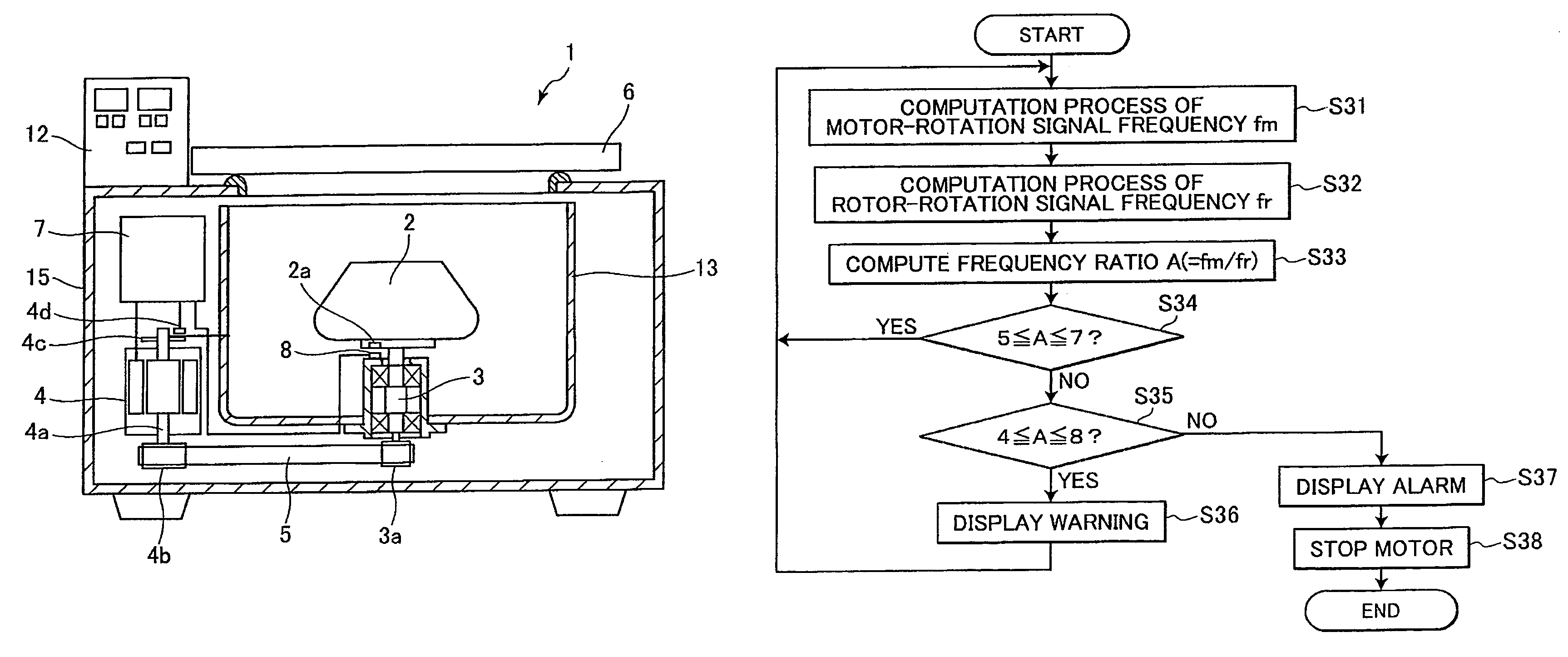
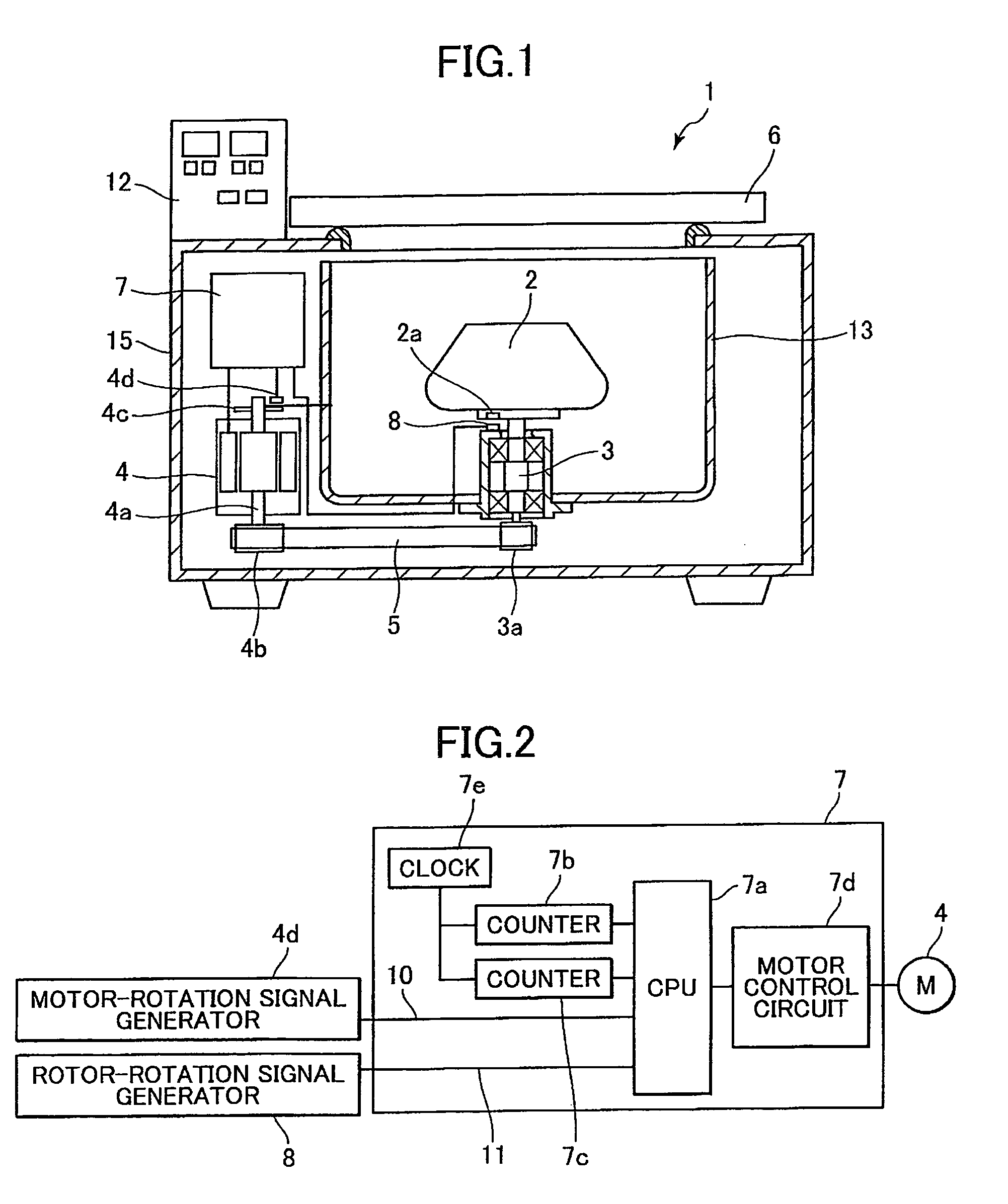
[0036]FIG. 1 is a cross-sectional view showing a centrifugal separator 1 in accordance with the first embodiment. The centrifugal separator 1 has a housing 15 in which an operation chamber 13 is housed. A rotor 2 and its rotational shaft 3 are disposed inside the operation chamber 13. The rotational shaft 3 is vertically oriented and rotatably supported on the bottom wall of the operation chamber 13. The lower end portion of the rotational shaft 3 penetrates into and extends outwardly of the bottom wall of the operation chamber 13. A pulley 3a is fixedly attached to the lower end of the rotational shaft 3. The rotor 2 is detachably mounted on the top end portion of the rotational shaft 3 to be rotatable therewith.

[0037]A motor 4, a belt 5, and a control unit 7 are disposed outside the operation chamber 13 but inside the housing 15. The motor 4 has a driving shaft 4a...

second embodiment

[0078]As described, the second embodiment alerts the user of the first stage of malfunction by not only performing the warning display but also lowering the motor torque if the motor torque has not been lowered 10%. While lowering the motor torque prolongs the acceleration or deceleration period of time and thus lowers the property of the centrifugal separator, it is advantageous in that the rotor can still be accelerated up to a target rotational speed set by the user. As such, the slightly deteriorated belt can still be used without need for immediate replacement of the belt 5 or immediate tension adjustment. It is further advantageous in that lowering the motor torque lessens the progress of the belt wear.

[0079]Although the present invention has been described with respect to specific embodiments, it will be appreciated by one skilled in the art that a variety of changes may be made without departing from the scope of the invention. For example, in the centrifugal separator in ac...


PUM

PropertyMeasurementUnit
frequencyaaaaaaaaaa
driving poweraaaaaaaaaa
torqueaaaaaaaaaa

Abstract

In a centrifugal separator of the type in which driving power of a motor is transmitted to a rotor via a power transmission mechanism, such as a belt, a motor-rotation signal frequency fm and a rotor-rotation signal frequency fr are computed, on the basis of which a frequency ratio A (fr / fm) is computed. When the frequency ratio A exceeds the upper limit of a first predetermined range, a warning message is displayed to prompt the user to perform maintenance. When the frequency ratio A exceeds the upper limit of a second predetermined range, an alarm message is displayed and the motor is stopped.

Description

BACKGROUND OF THE INVENTION[0001]1. Field of the Invention[0002]The present invention relates to a centrifugal separator, and more particularly to a belt driven centrifugal separator in which driving power of a motor is transmitted to a rotor via a driving power transmission mechanism, such as belt.[0003]2. Description of the Related Art[0004]Rotor driving systems of a centrifugal separator can be classified into a direct driving type in which a rotor is directly coupled to the rotational shaft of the motor, and an indirect driving type in which the rotor and the motor are coupled via a driving power transmitting mechanism including, for example, a belt. The centrifugal separator of the direct driving type is more frequently used in the art than that of the indirect driving type due to simplicity in structure and high driving power transmission efficiency. However, the direct driving type centrifugal separator requires a motor to be disposed in alignment with the rotational shaft of...

Claims


Application Information

Patent Timeline
Patent Type & Authority Patents(United States)
IPC IPC(8): B04B9/10B04B5/02
CPCB04B9/10B04B13/00Y10S388/924B04B9/02B04B9/08
Inventor FUJIMAKI, TAKAHIROTAKAHASHI, HIROYUKI
Owner KOKI HLDG CO LTD
Why Eureka
Try Eureka