Circuit for connection of at least two signal sources with at least one signal output

a technology of at least one signal source and at least one signal output, which is applied in the direction of electronic switching, pulse technique, electrical apparatus, etc., can solve the problems of limiting the number of usable surface coils, disadvantageous use of larger coils, and limiting the number of preamplifiers that are connected with the surface coils, so as to achieve high resistance in the conductors and effectively disconnect lines

Inactive Publication Date: 2008-05-13
SIEMENS AG
View PDF7 Cites 3 Cited by
  • Summary
  • Abstract
  • Description
  • Claims
  • Application Information

AI Technical Summary

Benefits of technology

[0006]An object of the present invention is to provide a simple circuit for connection of at least two signal sources with at least one signal output.
[0008]The blocking units block or enable the respective connection between the signal source and the signal output. The appropriate connection of the signal source with the signal output is also simultaneously enabled by the control signals of the control unit that serve for activation and deactivation of the signal sources. No separate switch controller is necessary, which allows a lower circuit complexity.
[0009]In an advantageous embodiment of the invention, the circuit has at least one primary line that is connected with the signal output and with which each signal source is connected via a secondary (branch) line. This design is particularly simple to execute since here a plurality of signal sources can be connected with the signal output with low circuit complexity.
[0013]Preferably the blocking elements are PIN diodes. High resistances in the conductors, which effectively disconnect the lines, can be achieved in a simple manner by control signals by means of such PIN diodes.

Problems solved by technology

The use of larger coils is disadvantageous because, in this case, the signal-to-noise ratio is significantly smaller in comparison to smaller coils.
In most magnetic resonance apparatuses, the number of the preamplifiers that are connected with the surface coils is the limiting factor for the number of usable surface coils.
A disadvantage of this known circuit is its high circuit complexity.

Method used


Image

  • Circuit for connection of at least two signal sources with at least one signal output
  • Circuit for connection of at least two signal sources with at least one signal output
  • Circuit for connection of at least two signal sources with at least one signal output

Examples


Embodiment Construction

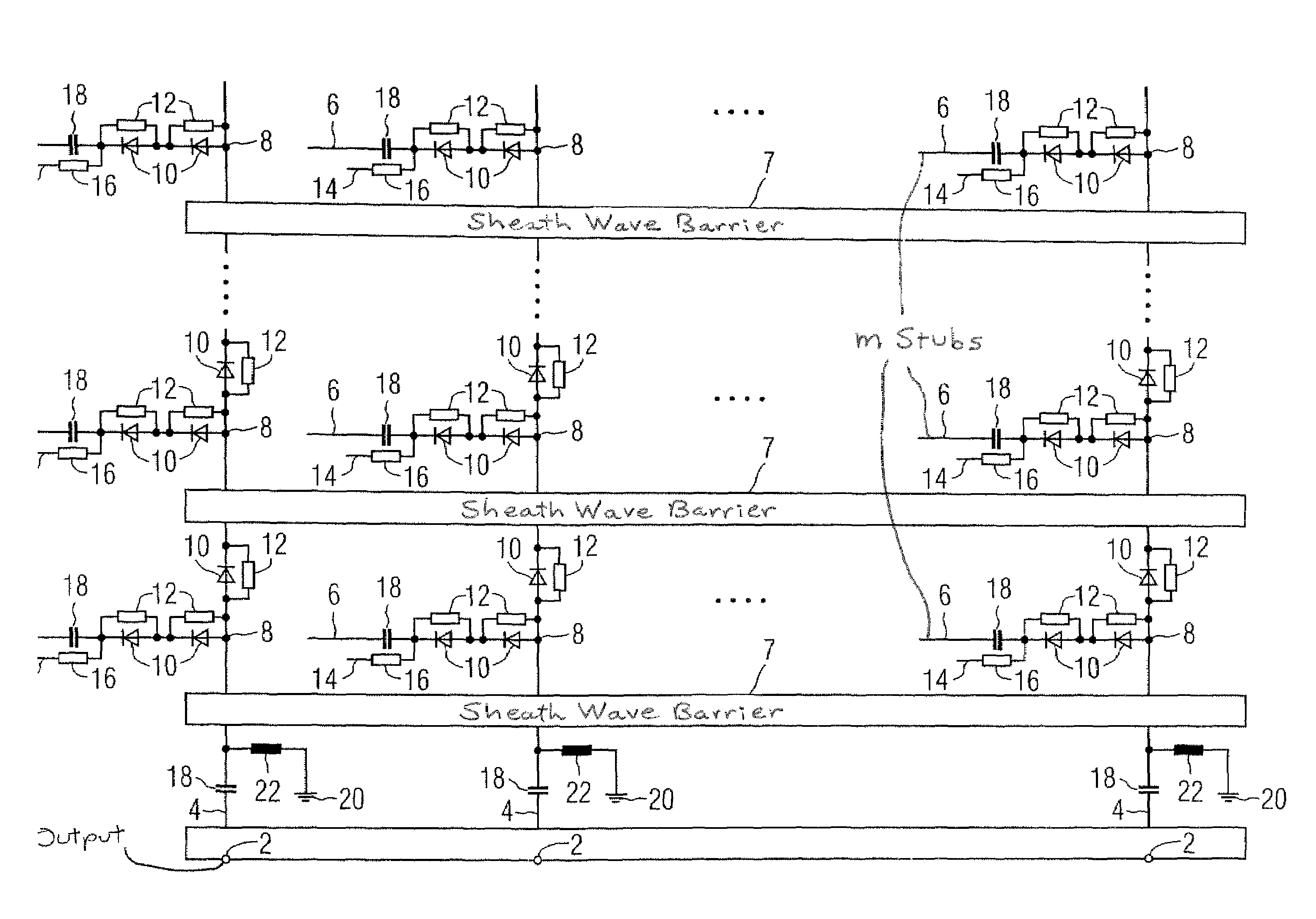
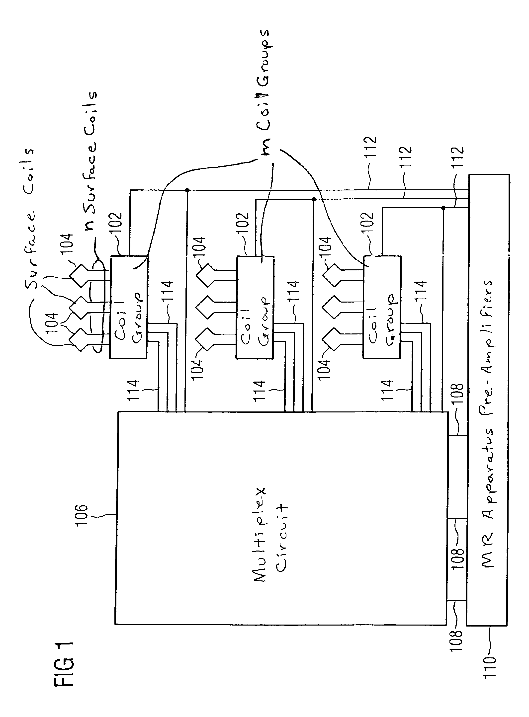
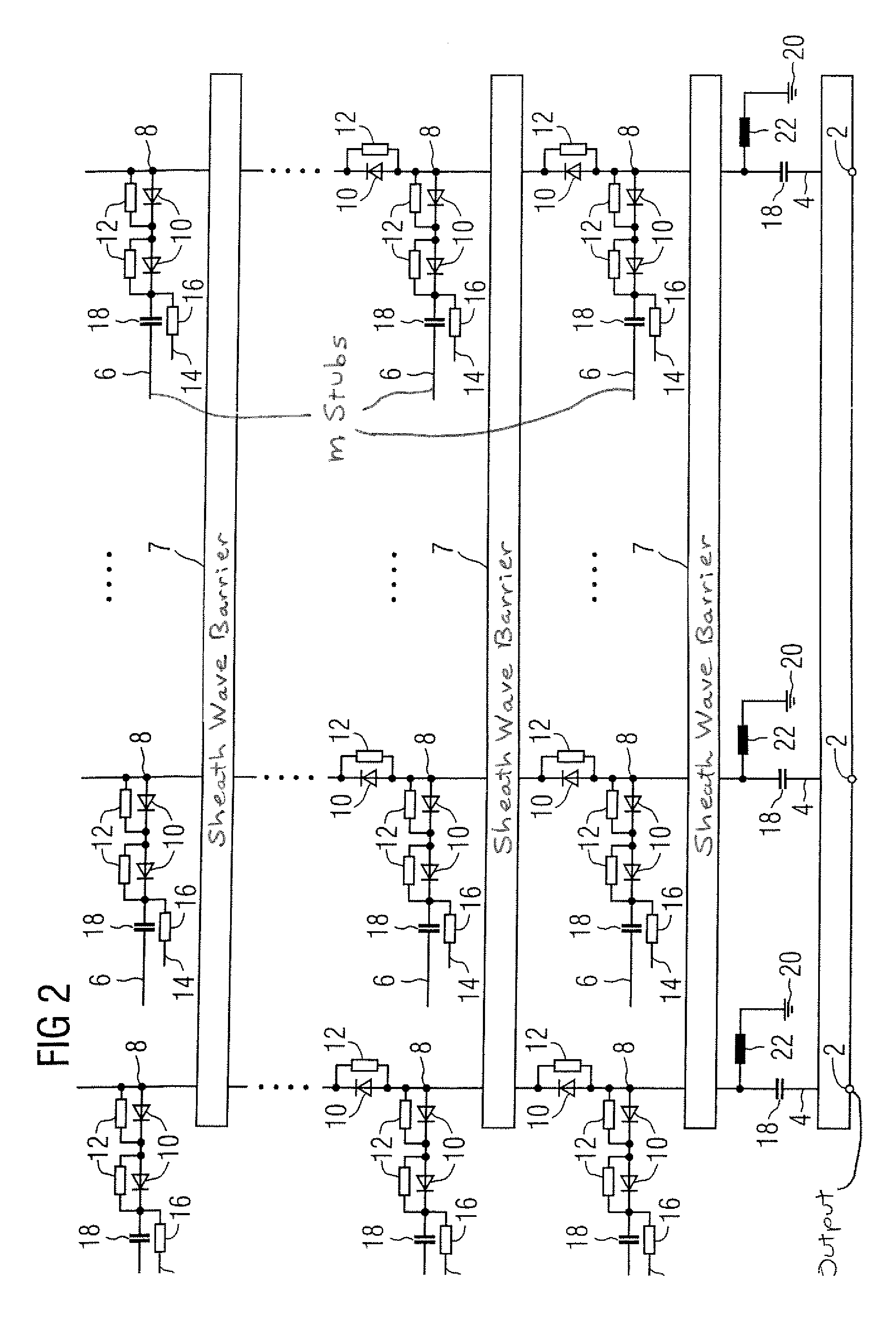
[0016]The system schematically shown in FIG. 1 has m coil groups 102 (m being an integer), of which three are shown. Each coil group 102 has n surface coils 104 (n being an integer) for the reception of magnetic resonance signals. Again only three surface coils 104 are shown. The surface coils 104 of the coil group 102 are connected with n signal outputs 108 (of which three are likewise shown) by a multiplex circuit 106. The multiplex circuit 106 is a preferred embodiment of the invention and is further explained in detail below using FIG. 2. The n signal outputs 108 are connected with n preamplifiers of a magnetic resonance apparatus 110, with the preamplifiers of the magnetic resonance apparatus 110 being shown only as a single block. Since the number of surface coils 104 of a coil group 102 is equal to the number of preamplifiers, magnetic resonance signals can be acquired with any complete coil group 102. For this purpose, the n surface coils 104 thereof are tuned to the corresp...


PUM


Abstract

In a circuit for connection of at least two signal sources with at least one signal output, the signal sources are connected with a control unit. The control unit activates or deactivates the signal sources by transmission of control signals. Each signal source is connected with a blocking unit. Each blocking unit is connected with the control unit. The blocking unit can block or enable a connection between the signal source and the signal output, with the connection being automatically enabled when the signal source is activated.

Description

BACKGROUND OF THE INVENTION[0001]1. Field of the Invention[0002]The present invention concerns a circuit for connection of at least two signal sources with at least one signal output, the signal sources being connected to a control unit that activates or deactivates the signal sources via transmission of control signals.[0003]2. Description of the Prior Art[0004]In the transmission of electrical signals from signal sources to a signal output that, for example, is connected to a signal evaluation unit, it is frequently necessary to selectively connect a number of signal sources with only one signal evaluation unit. This is in particular the case in magnetic resonance apparatuses where it is necessary to connect a large number of surface coils with a lesser number of preamplifiers. It is additionally necessary that only a few or only one single surface coil are / is active at the same time in order to prevent crosstalk from the other surface coils. The large number of surface coils is, ...

Claims


Application Information

Patent Timeline
Patent Type & Authority Patents(United States)
IPC IPC(8): H01P1/15
CPCH03K17/76
Inventor KESS, HELMUT
Owner SIEMENS AG
Why Eureka
Try Eureka