Mobile station capable of and a method for generating chip patterns for transmission

a mobile station and chip pattern technology, applied in the field of wireless transmission technology, can solve the problems of difficult to increase the spectral usage efficiency in the multi-cell environment and the isolated cell environment, and achieve the effects of increasing the spectral usage efficiency, increasing the link capacity, and increasing the link capacity

Inactive Publication Date: 2008-05-13
NTT DOCOMO INC
View PDF12 Cites 43 Cited by
  • Summary
  • Abstract
  • Description
  • Claims
  • Application Information

AI Technical Summary

Benefits of technology

[0044]A method of wireless transmission in an embodiment of the invention enables a reduction in transmitting signals interfering with one another as the frequency spectrums of the respective mobile stations are frequency-domain orthogonal even in a case of multiple mobile stations simultaneously connecting to the same base station. Such reduction of multiple-access interference increases the spectral usage effic...

Problems solved by technology

However, as DS-CDMA is a wireless access method suitable in the multi-cell environment, there is a problem as described below as a cause for concern.
However, in an actual uplink wireless propagation environment, an effect of Multiple-Access Interference (MAI) in which the signals from the respective mobile stations interfere with one another due to differences in condition of propagation from the respective mobile stations to the base station (for instanc...

Method used


Image

  • Mobile station capable of and a method for generating chip patterns for transmission
  • Mobile station capable of and a method for generating chip patterns for transmission
  • Mobile station capable of and a method for generating chip patterns for transmission

Examples


first embodiment

A First Embodiment

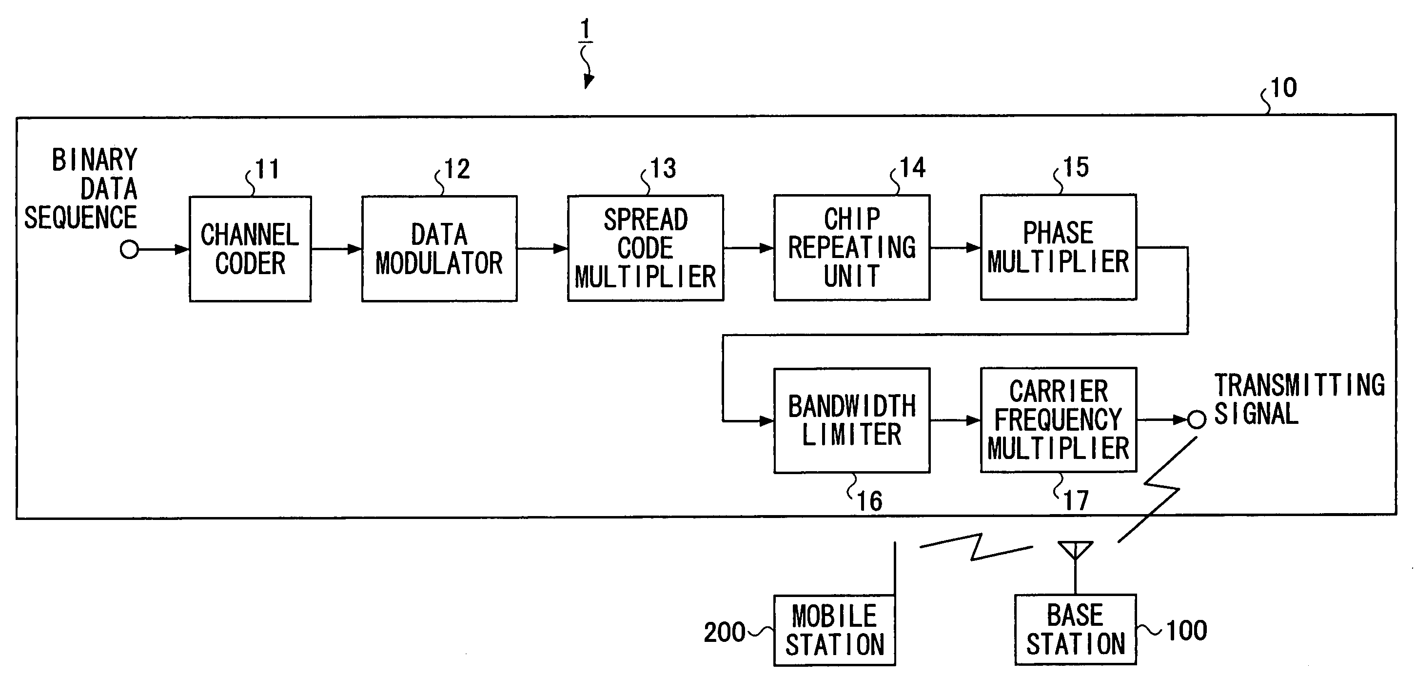
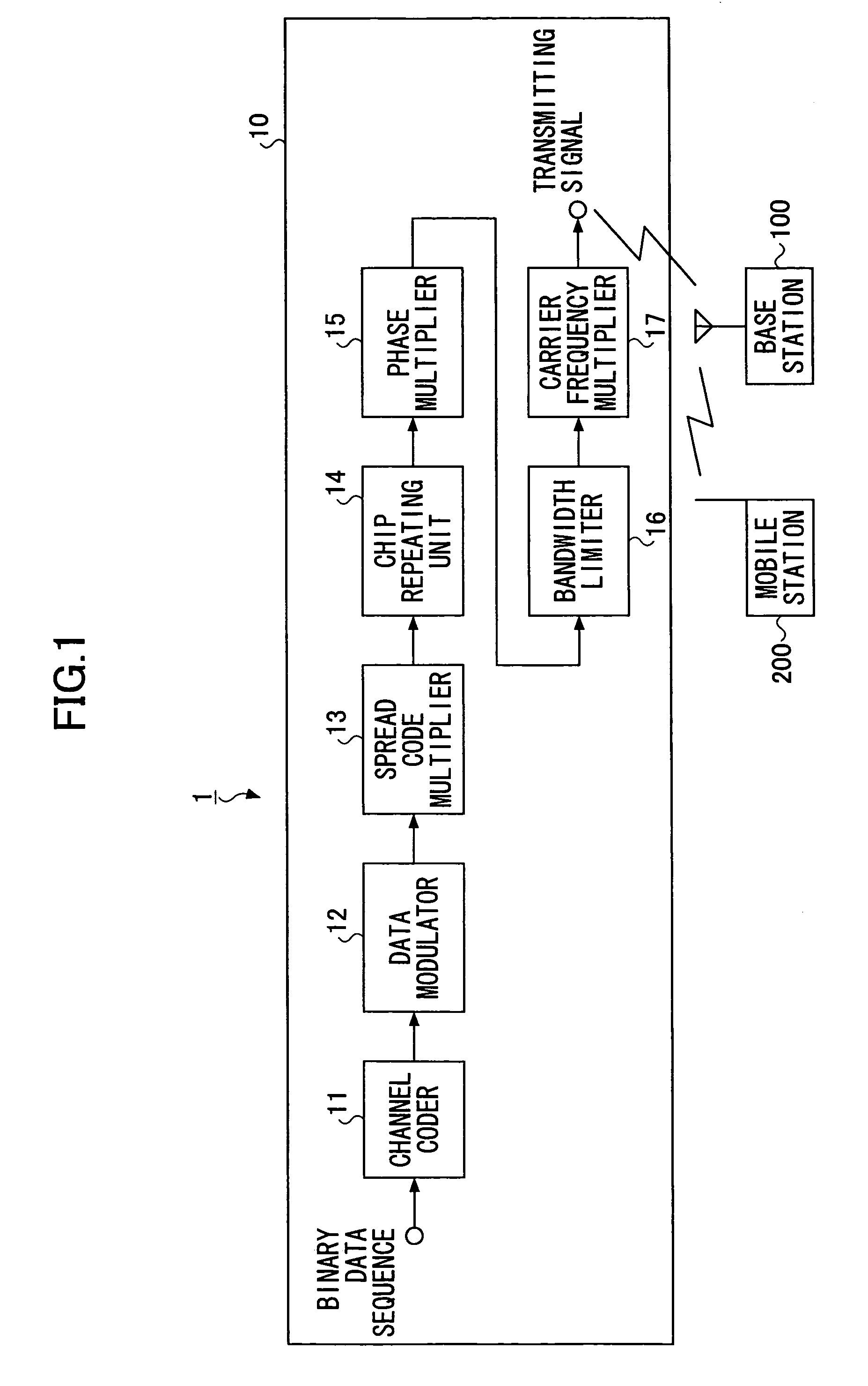
[0093]First, a configuration of a wireless transmission system according to a first embodiment is described. As illustrated in FIG. 1, a wireless transmission system 1 includes a mobile station 10 and a base station 100. The mobile station 10 transmits a wireless signal spread by multiplying spreading code. The mobile station 10 includes a channel encoder 11, a data modulator 12, a spreading-code multiplier 13, a chip repetition unit 14, a phase multiplier 15, a bandwidth limiter 16, and a carrier-frequency multiplier 17.

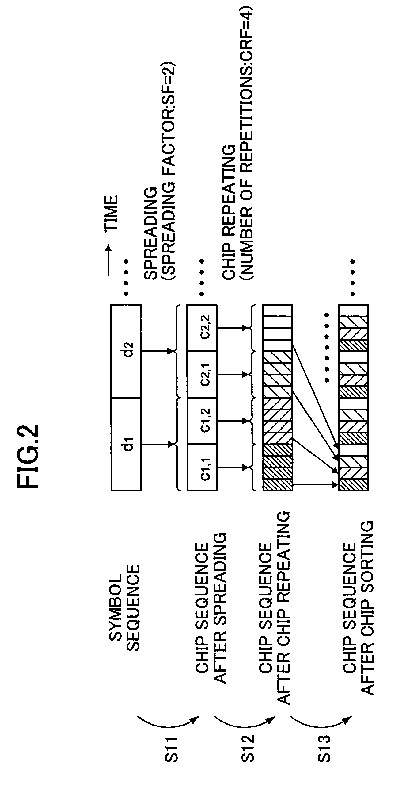
[0094]The channel encoder 11 performs channel coding by applying error-correction code such as Turbo code and convolution code. The data modulator 12 modulates the channel-coded data. The spreading-code multiplier 13 multiplies spreading code to the modulated data so as to generate spreading-chip sequence. The chip-repetition unit 14 performs chip repetition for a predetermined number of repetitions to the spreading-chip sequence so as to generate ...

second embodiment

A Second Embodiment

[0099]While an exemplary aspect of applying on a fixed basis SF=2 as the spreading factor and CRF=4 as the number of repetitions is illustrated in the first embodiment, in a wireless transmission system according to the present embodiment, a mobile station comprises a function of variably controlling spreading factor of spreading code and the number of chip repetitions.

[0100]A wireless transmission system 2 according to the second embodiment has the same basic configuration as the wireless transmission system 1 as detailed in the first embodiment. Therefore, numerals of the same column (with the same tail-ends) are assigned to the mobile station and its elements so as to omit the description while detailing below the differences from the first embodiment, referring to FIG. 4 and FIG. 5.

[0101]FIG. 4 is a schematic diagram of an overall configuration of the wireless transmission system 2 and a configuration of a mobile station 20 according to the present embodiment....

third embodiment

A Third Embodiment

[0107]While an exemplary aspect which variably controls the spreading factor and the number of chip repetitions based on the spreading factor and the number of chip repetitions reported from the base station is shown in the second embodiment, the mobile station comprises a function of variably controlling the spreading factor and the number of chip repetitions based on the cell environment reported from the base station in the wireless transmission system according to the present embodiment.

[0108]A wireless transmission system 3 according to the third embodiment has the same basic configuration as the wireless transmission system 2 detailed in the second embodiment. Therefore, numerals of the same column (with the same tail-ends) are assigned to the mobile station and its elements so as to omit the description as well as detailing below the differences from the second embodiment, referring to FIG. 6 through FIG. 8.

[0109]FIG. 6 is a diagram of an overall configurati...


PUM


Abstract

A mobile station that wirelessly transmits to a base station by DS-CDMA a signal spread by multiplying a spreading code includes a chip-pattern generating unit that generates a predetermined chip pattern by performing chip repetition for a predetermined number of repetitions to a spreading chip sequence, and a multiplying unit that multiplies to a signal including the predetermined chip pattern generated by the generating unit a phase specific to the mobile station.

Description

BACKGROUND OF THE INVENTION[0001]1. Field of the Invention[0002]The present invention generally relates to a technology for wireless transmission, and particularly relates to a mobile station, a base station, and a program for and a method of wireless transmission.[0003]2. Description of the Related Art[0004]The development of a fourth-generation mobile communications method, which is the next-generation mobile communications method beyond IMT-2000 (International Mobile Telecommunications-2000), has been underway. A fourth-generation mobile communications method flexibly supporting a multi-cell environment including a cellular system, as well as an isolated cell environment such as a hot-spot area and an indoor environment so as to seek a further increase in spectral usage efficiency at the respective cell environments, is being desired.[0005]As a candidate wireless access method in the fourth-generation mobile communications which is applied to a link from a mobile station to a bas...

Claims


Application Information

Patent Timeline
IPC IPC(8): H04B1/69H04L27/04H04B1/707H04B1/7097H04J11/00H04J13/12H04J13/16H04L25/03H04L27/01H04W72/04H04W76/02
CPCH04B1/69H04B1/7097H04B1/692H04L2025/03522H04B2201/70703H04B2201/709709H04L25/03006H04B2201/70701A47G19/2227A47G21/04A47G21/14A47G2400/02
Inventor ATARASHI, HIROYUKISAWAHASHI, MAMORUKAWAMURA, TERUO
Owner NTT DOCOMO INC
Why Eureka
Try Eureka