Goniometric sensor

a sensor and goniometer technology, applied in the field of goniometers, can solve the problems of limited applicability of sensors in special fields, limited application of sensors, and limited range of application,

Inactive Publication Date: 2008-05-20
BERGAMASCO MASSIMO +3
View PDF15 Cites 18 Cited by
  • Summary
  • Abstract
  • Description
  • Claims
  • Application Information

AI Technical Summary

Benefits of technology

[0020]It is another object of the present invention to provide a goniometric sensor that is structurally simple and cost effective.

Problems solved by technology

The nature of the sensors mentioned above remarkably limits the applicability in special fields such as, for example, virtual reality or the design of artificial prosthesis in medicine.
In particular, such sensors are not suitable in fields that, owing to technological progress, have recently captured the attention of many researchers, i.e. acquisition and analysis of movement of human body parts.
In particular, the limbs with greater volume, such as arms and legs of a human, have few degrees of freedom and the devices used for detecting their motion usually have higher weight and encumbrance and require a higher rate of precision.
The limbs with smaller volume, instead, such as the fingers of the hand that have a higher number of degrees of freedom, cannot be monitored with heavy and bulky devices and require less precision.
In particular, they have high costs and have the further drawback of being particularly sensitive to the presence of metal that can distort the magnetic field.
Usually, the optical devices are less bulky than the magnetic, but their functionality can be affected by parts of the body that cross accidentally the path of the light.
Another drawback of the optical devices are high costs and the need for a post-processing of the measured data, as well as the long set up time for calibrating the measuring equipment.
Their performances are high but they have reliability problems and a high cost;
Such sensors have a relatively low cost but have reliability problems and low measuring precision.

Method used


Image

  • Goniometric sensor
  • Goniometric sensor
  • Goniometric sensor

Examples


Embodiment Construction

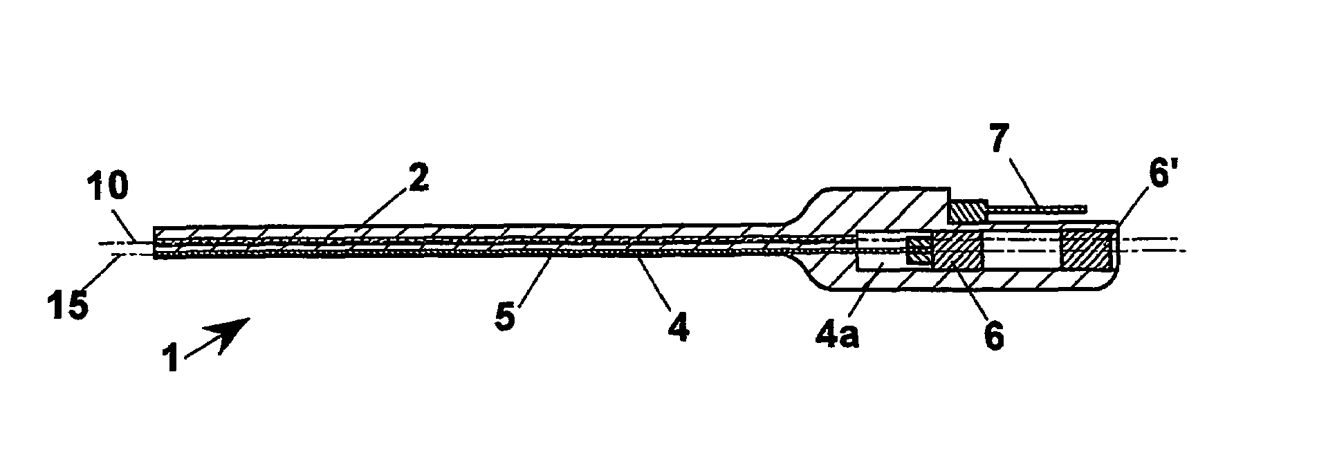
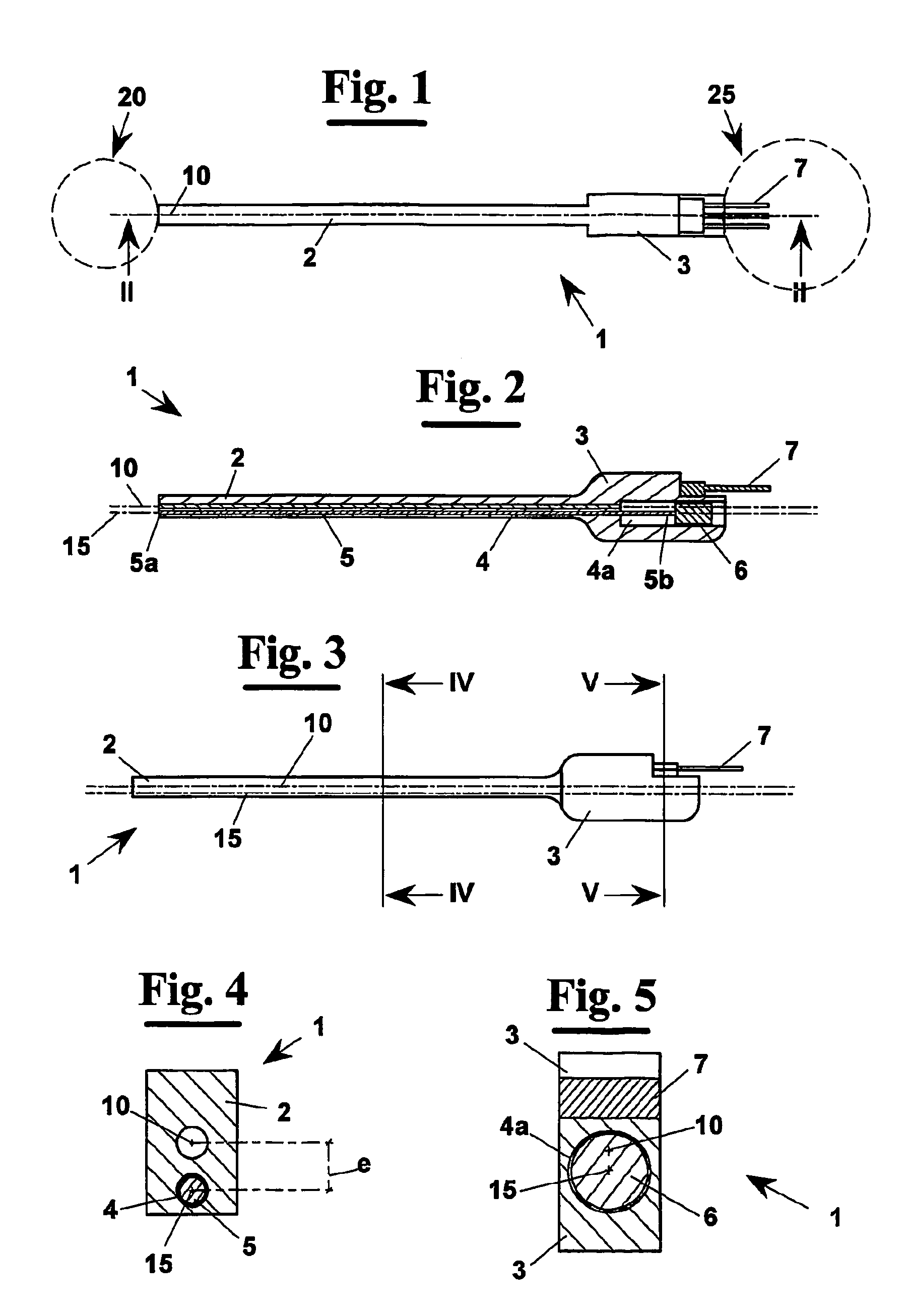
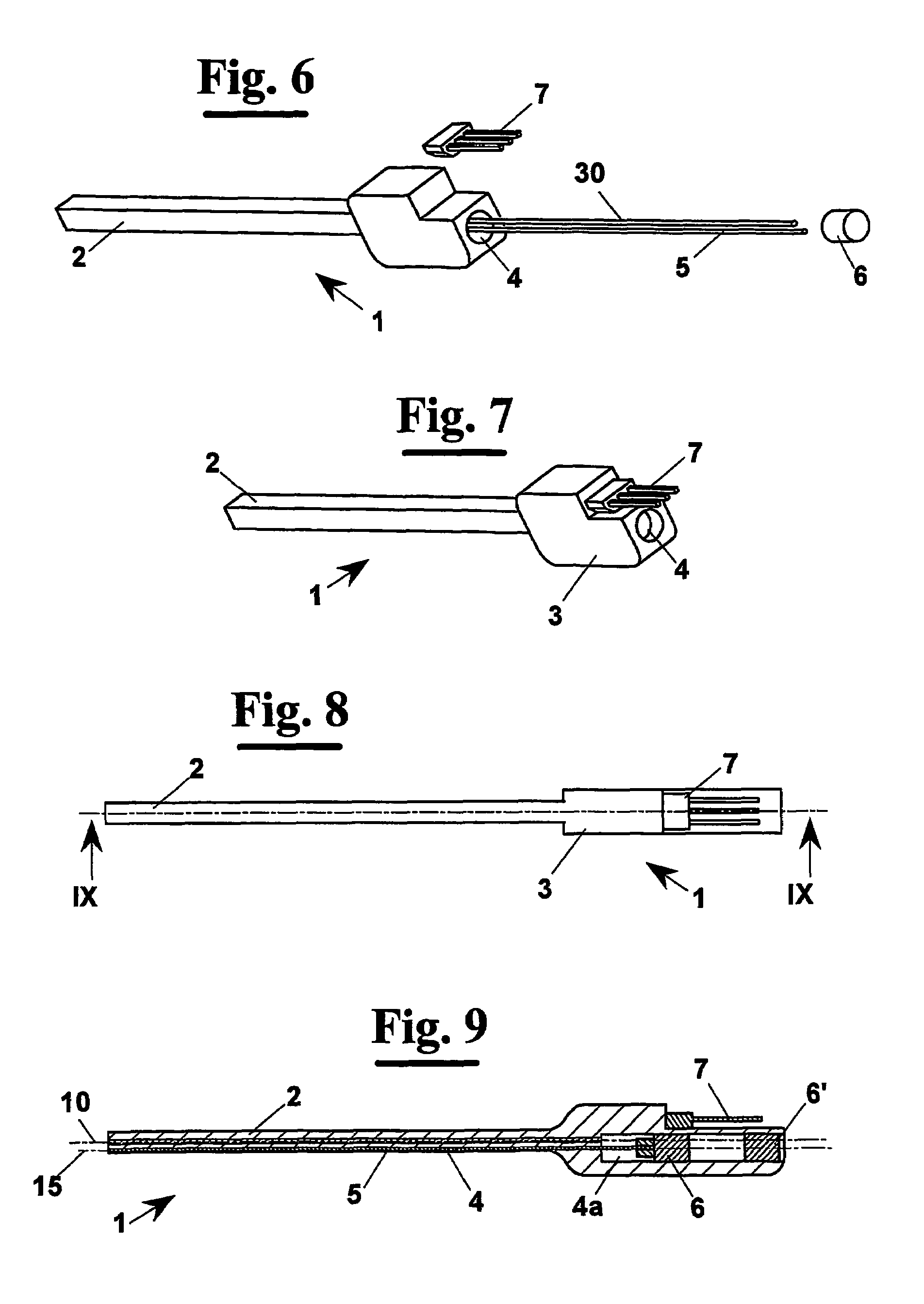
[0048]With reference to FIGS. 1 and 2, a sensor for goniometric measures 1, according to the present invention, measures the relative rotation of two bodies 20 and 25, symbolically indicated with circles in FIG. 1.

[0049]In particular, sensor 1 comprises a flexible elongated element 2 whose respective ends are connected to bodies 20 and 25. Goniometric sensor 1 has an axis of symmetry 10 that is the same of element 2. At the bending of element 2, the axis 10 becomes also neutral axis, i.e. it has lines that do not lengthen or shorten when bending. Furthermore, numeral 15 indicates a generic line that is eccentric with respect to the neutral axis.

[0050]When bodies 20 and 25 rotate with respect to each other, flexible elongated element 2 is subject to a bending that produces a length variation of the lines different from the neutral axis 10. In particular, a line coincident to eccentric line 15 is subject to a length variation ΔL (FIG. 10). It must be noted that the neutral axis change...


PUM


Abstract

A goniometric sensor (1) for measuring the relative rotation of two objects (20,25) comprising a flexible elongated element (2) whose respective ends are connected to the two objects (20, 25) and during whose bending the length variation ΔL is determined of one of the lines (15) not located at the neutral axis (10). This length variation ΔL is directly proportional to the relative rotation (α) between the two bodies (20, 25) multiplied for the eccentricity (e) of the line (15) with respect to the neutral axis (10). Therefore, it is possible to determine easily the relative rotation (α) by knowing the length L and the eccentricity (e) with respect to the neutral axis 10, and measuring the length variation ΔL of the line, for example by measuring the movement of the end of a cable located in a hole that contains the line.

Description

[0001]This application is a filing under 35 USC 371 of PCT / IB2002 / 005665, Dec. 30, 2002.FIELD OF THE INVENTION[0002]The present invention generally relates to a device for determining the angle of rotation of an object moving in space with respect to a reference object.[0003]In particular, the invention relates to a device for determining the relative angular position of two bodies moving in space with respect to each other.BACKGROUND OF THE INVENTION[0004]Various electro-mechanical sensors exist used for measuring angular position between two bodies rotating with respect to each other. However, such sensors usually measure the relative angular position of bodies mechanically connected by rigid joints, for example the steering wheel and the transmission shaft of a car.[0005]The nature of the sensors mentioned above remarkably limits the applicability in special fields such as, for example, virtual reality or the design of artificial prosthesis in medicine.[0006]In particular, such s...

Claims


Application Information

Patent Timeline
Patent Type & Authority Patents(United States)
IPC IPC(8): G01B3/56A61B5/103A61F2/58A61F2/68A61F2/76
CPCA61B5/1071A61B5/4528A61F2/68A61F2/583A61F2/586A61F2002/7625A61B5/6806A61B5/6824
Inventor BERGAMASCO, MASSIMOIT), SALSEDO, FABIOULLRICH, GUENTHER NINOVILLELLA, PAOLO
Owner BERGAMASCO MASSIMO
Why Eureka
Try Eureka