
Projectile with tail-mounted gas generator assembly

Inactive Publication Date: 2008-05-20
THE UNITED STATES OF AMERICA AS REPRESENTED BY THE SECRETARY OF THE NAVY
View PDF13 Cites 3 Cited by
  • Summary
  • Abstract
  • Description
  • Claims
  • Application Information

AI Technical Summary

Benefits of technology

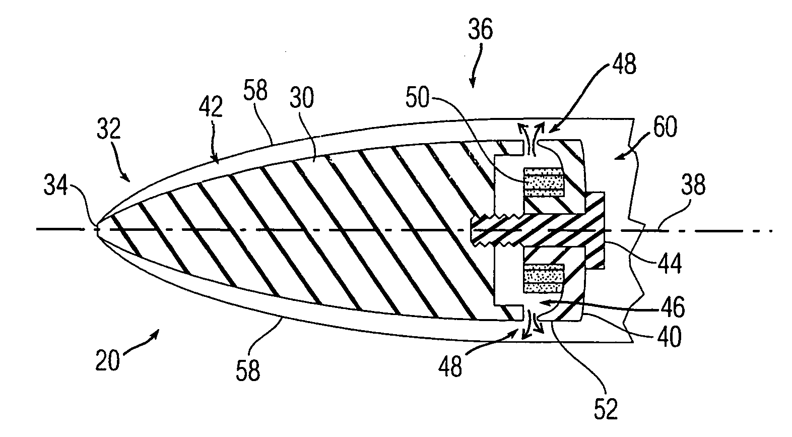
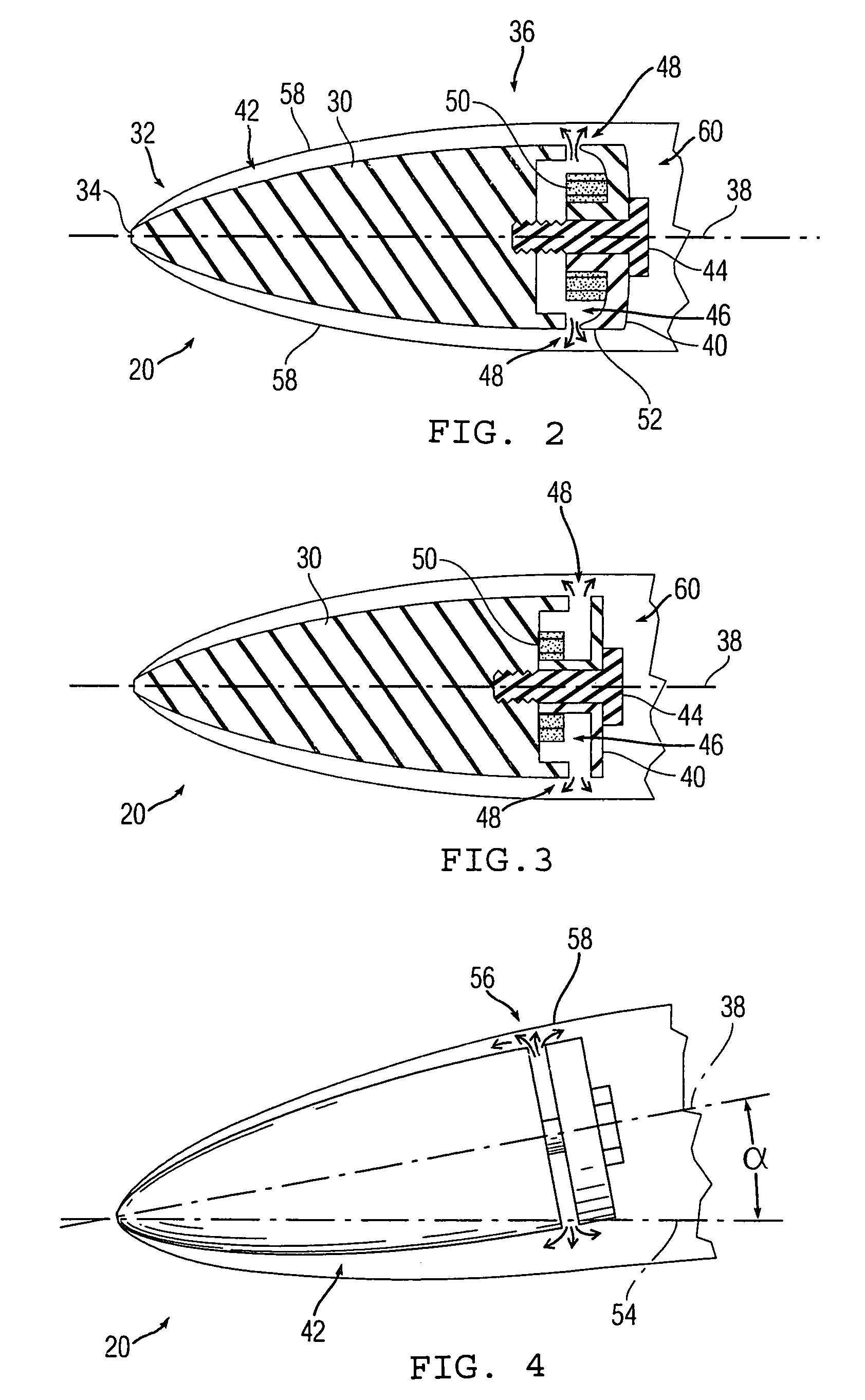
[0013]The present teachings also provide a method of stabilizing a moving projectile. The method provides a gas generator assembly on a rear end portion of a projectile. The gas generator assembly defines at least one radial discharge aperture that can be arranged in fluid communication with a combustion chamber. A gas is generated by igniting a combustible material arranged in the combustion chamber and is discharged from the combustion chamber through the least one radial discharge aperture to an area that is exterior to the body of the projectile. The discharged gas is directed to impinge against a wall of a cavity formed by the moving projectile to form a reactive force that stabilizes the projectile.
[0014]By discharging a gas at the rear portion of the projectile, the occurrence of tail-slap can be reduced or eliminated. Moreover, improved accuracy and stability, and an extended range can be achieved.

Problems solved by technology

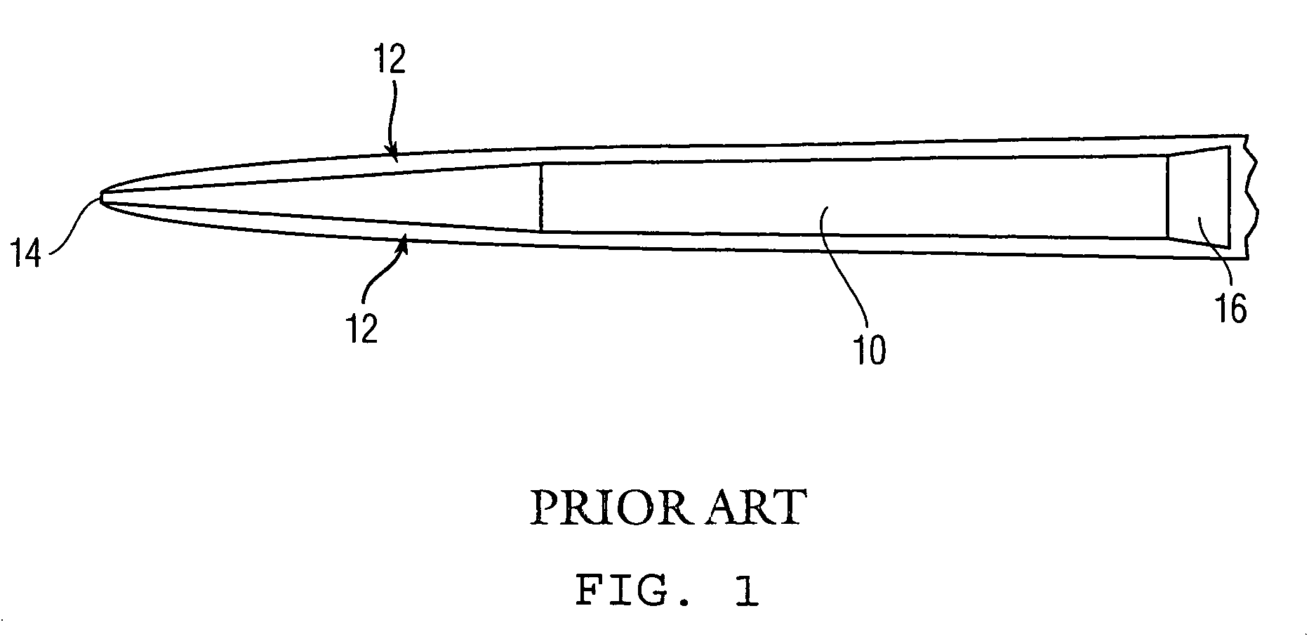
However, if the body of the projectile is perturbed and begins to yaw, substantially no restoring forces are experienced until the flared afterbody comes into contact with the cavity wall.
As the projectile begins to travel down-range, it begins to slow due to drag generated at the tip, resulting in the size of the cavity shrinking.
Consequently, projectiles are incapable of traveling the same distance at a greater depth compared to a shallower depth.
However, the Miskelly reference does not disclose a way of eliminating the occurrence of tail-slap during travel of the projectile.

Method used


Image

  • Projectile with tail-mounted gas generator assembly
  • Projectile with tail-mounted gas generator assembly
  • Projectile with tail-mounted gas generator assembly

Examples


Embodiment Construction

[0021]Underwater gun systems can be used as anti-mine and anti-torpedo devices. Such gun systems can be composed of, for example, underwater projectiles, an underwater gun, a ship-mounted turret, a targeting system, and / or a combat system. The underwater gun can be arranged to shoot projectiles that are designed to neutralize undersea targets from relatively long range, such as, for example, from about 200m. The undersea targets can be identified and localized by way of specialized targeting systems. Moreover, the targeting systems can provide the control commands for directing the ship-mounted turret to point the underwater gun towards the targets. The present teachings provide a projectile that can be used with an underwater gun system, or the like, having an improved accuracy and stability, and an extended range. The present teachings can be applied to and encompass other airborne or underwater devices, self-propelled or not self-propelled, such as, torpedoes, bullets, missiles, ...


PUM


Abstract

A projectile is provided that includes a body having a front tip portion and a rear end portion. A combustion chamber base plate is operatively arranged with the rear end portion of the body and defines a combustion chamber. At least one radial discharge aperture is partially defined by the combustion chamber base plate and is arranged in fluid communication with the combustion chamber. A gas generated by igniting a combustible material is discharged through the at least one radial discharge aperture. The discharged gas impinges against a wall of a cavity formed by the moving projectile to form a reactive force that stabilizes the projectile thereby reducing the occurrence of tail-slap.

Description

STATEMENT OF GOVERNMENT INTEREST[0001]The teachings described herein may be manufactured and used by or for the Government of the United States of America for governmental purposes without the payment of any royalties thereon or therefore.BACKGROUND OF THE INVENTION[0002](1) Field of the Invention[0003]The present teachings relate to an underwater projectile for neutralizing undersea targets from a relatively long range. More particularly, the present teachings relate to the tail or end portion of a supercavitating projectile and to arrangements and methods for emitting gases from the end portion to stabilize the projectile and reduce viscous drag.[0004](2) Description of the Prior Art[0005]Projectiles fired from underwater guns can effectively travel large distances by making use of supercavitation. Supercavitation occurs when a body, such as a projectile, travels through water at a relatively high-speed and a vaporous cavity begins to form at its tip. With proper projectile design...

Claims


Application Information

Patent Timeline
IPC IPC(8): F42B15/20
CPCF42B10/668F42B19/01F42B19/00
Inventor GIESEKE, THOMAS J.
Owner THE UNITED STATES OF AMERICA AS REPRESENTED BY THE SECRETARY OF THE NAVY
Learn More