Gas sensor

a gas sensor and optical technology, applied in the field of optical gas sensors, can solve the problems of high required degree of led radiation suppression, complex filter manufacturing, and high cost, and achieve the effects of increasing the sensitivity and range of the sensor, enhancing the efficiency of source radiation conversion, and increasing the sensitivity of the sensor

Active Publication Date: 2014-06-03
BAH HLDG LLC
View PDF15 Cites 12 Cited by
  • Summary
  • Abstract
  • Description
  • Claims
  • Application Information

AI Technical Summary

Benefits of technology

[0012]By using an optics assembly to converge (e.g. focus) the radiation emitted by the radiation source away from the luminescence detector assembly in this way, the intensity of such “source” radiation arriving at the detector is significantly reduced. As such, the need for high suppression of the source radiation is correspondingly reduced, and sufficient optical filtering can be achieved by a simple and inexpensive filter such as a semi-transparent film of appropriate colour. In some cases, the need for a filter may be avoided altogether.
[0054]As described above, by providing a reference channel in this way, variations in the radiation output by the LED or other source can be compensated for. This significantly improves the accuracy and stability of the sensor.

Problems solved by technology

Filters of this sort are complex to manufacture and expensive.
However, the required degree of LED radiation suppression is still high since there is a lot of scattered light and hence it is still necessary to provide a high quality optical filter 6.

Method used


Image

  • Gas sensor
  • Gas sensor
  • Gas sensor

Examples


Embodiment Construction

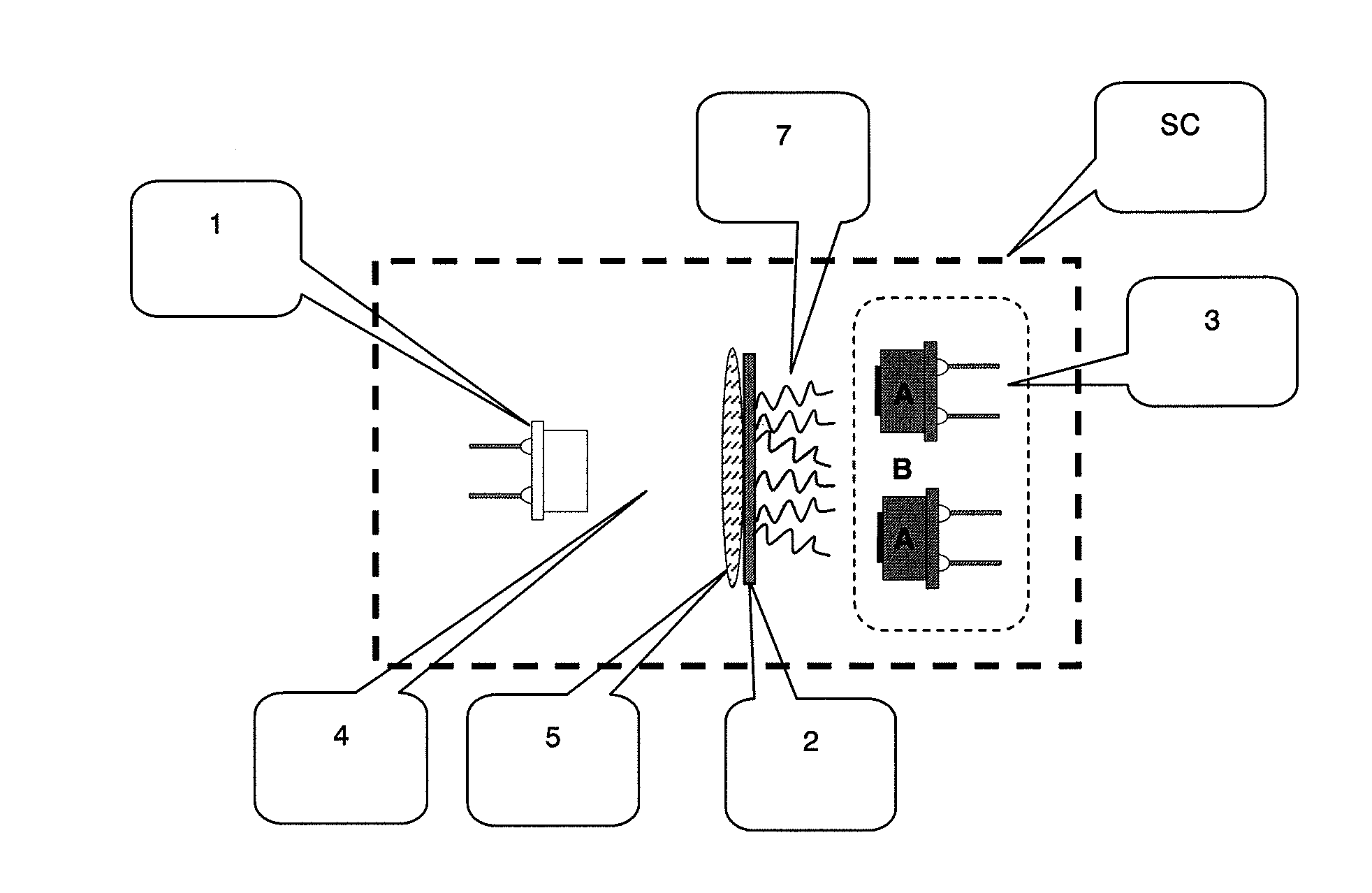
[0067]As described above, luminescent optical gas sensors can be used to measure the concentration of various target gases, including oxygen and carbon dioxide, through the use of a photoluminescent material which is sensitive to the target gas in question. Suitable photoluminescent materials are known for example from U.S. Pat. No. 6,682,935 and U.S. Pat. No. 5,728,422, both of which documents are incorporated herein by reference. Any of the gas-sensitive materials disclosed in either document could be used as the photoluminescent material referred to in the description below. The photoluminescent material could be fluorescent and hence the terms “luminescence” and “fluorescence” may be used interchangeably below. Preferably, the material emits the luminescence substantially instantaneously upon source radiation striking the material.

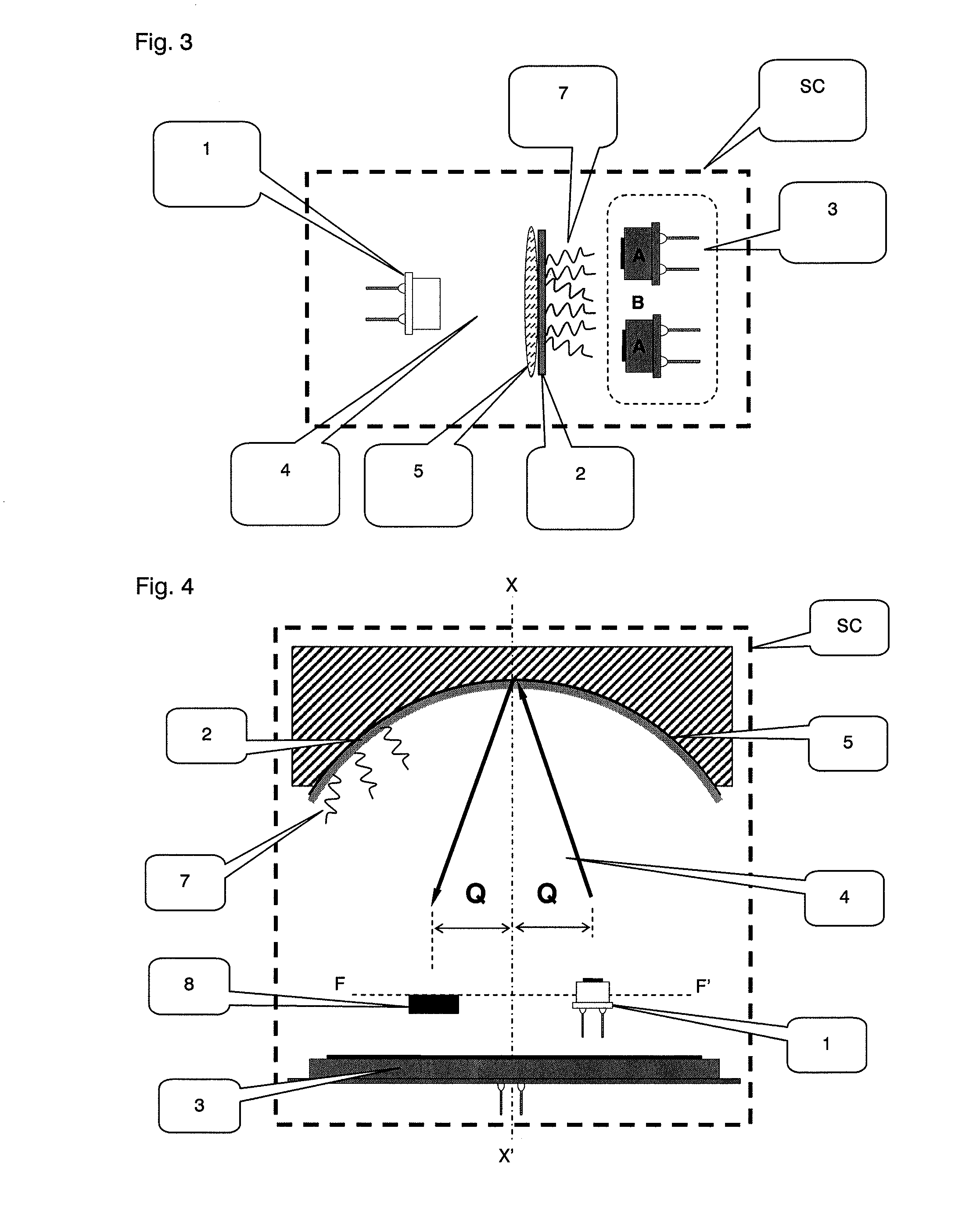
[0068]FIG. 3 shows a first embodiment of a gas sensor utilising the presently disclosed techniques. Like reference numerals are used for components al...


PUM


Abstract

In one aspect of the disclosure, a gas sensor is provided, comprising: a chamber for containing a gas sample in use, and a radiation source adapted to emit radiation within a first waveband. A photoluminescent material, upon absorption of radiation of a first wavelength within the first waveband, emits radiation of a second wavelength, the photoluminescent material being responsive to the presence of a target gas species in the gas sample. The gas sensor further comprises a luminescence detector assembly. The luminescence detector assembly is adapted to detect radiation of the second wavelength and output a corresponding measurement signal related to the concentration of the target gas species. An optics assembly is adapted to receive radiation emitted by the radiation source and to converge the radiation towards a location at which the luminescence detector assembly cannot receive radiation.

Description

FIELD OF INVENTION[0001]The present invention relates to optical gas sensors which utilise a gas-sensitive, photoluminescent material to determine the concentration of a gas of interest. Their operation is based on the fact that the intensity of the luminescence emitted by the photoluminescent material of the sensor depends on the concentration of the gas of interest. More particularly, the invention relates to improvement in design and performance of such sensors.BACKGROUND[0002]Luminescent (e.g. fluorescent) optical sensors are widely used in medicine, food processing and HVAC systems for determining the concentration of different gases such as oxygen, carbon dioxide and others. Examples of conventional fluorescent optical sensors are disclosed in U.S. Pat. No. 6,682,935 and U.S. Pat. No. 5,728,422.[0003]FIG. 1 depicts a representative example of a conventional sensor. A radiation source 1 such as a light-emitting diode illuminates a gas-sensitive, photoluminescent layer 2, which ...

Claims


Application Information

Patent Timeline
Patent Type & Authority Patents(United States)
IPC IPC(8): F21V9/16
CPCG01J3/51H01L31/0232G01N21/77G01J1/58H01L31/02322G01N21/3504G01N2021/7786
Inventor TKACHUK, MICHAEL
Owner BAH HLDG LLC
Why Eureka
Try Eureka