Systems and methods for making pipe liners

a technology of systems and methods, applied in the direction of pipe elements, mechanical equipment, transportation and packaging, etc., can solve the problems of cumbersome transport of site production, difficult to follow procedures, and increasing difficulty in continuing to use such metal articles

Active Publication Date: 2008-05-20
SMART PIPE COMPANY
View PDF86 Cites 31 Cited by
  • Summary
  • Abstract
  • Description
  • Claims
  • Application Information

AI Technical Summary

Benefits of technology

[0015]The present invention discloses, in at least certain aspects, a light-weight high-strength yet flexible multi-component pipe liner structure that can be installed as a stand-alone pipe liner restoring a pipe or a host pipeline to (or near) its original performance parameters and original service life, while providing increased internal and external corrosion protection and increased protection from damage, e.g. during earthquakes, accidents, and acts of terrorism. In certain aspects, a “stand-alone” pipe liner as used herein is a pipe liner that withstands all (or substantially all) installation and operational loads without assistance.
[0040]This placement results in an annular space between the pipe reinforcement and the inside of the cover sheet due to the presence therebetween of the fiber optic sensors. Spacers are, optionally, placed between the sensor tapes as necessary to support the cover (e.g., separate spacers made of plastic, wood, extruded thermoplastic or thermosetting material or spacers that are integral to a cover). Additionally, in certain aspects, these spacers are, optionally, shaped to permit the accumulation of permeated fluids from the flowing fluid to be vacuumed at an external vent port so there is no accumulation of pressure that might result in damage to the pipe liner. Monitoring the amount of fluid removed and / or pressure relieved provides an additional indication of the integrity of the pipe liner.

Problems solved by technology

However, with the population growing throughout the world and the necessity for transporting liquids and gases to more locations increases, the continued utilization of such metal articles has become more and more difficult for a number of reasons.
Such off-site production can require transport of cumbersome metal articles to an installation location and then subsequent placement into already-dug channels.
These procedures can be difficult to follow since metal articles are rather heavy and must be connected together to form the desired pipeline.
Additionally, in order to reduce the number of connections between individual pipes, longer metal pipes could be formed, which adds to the complexity with an increase in required welded connections.
Further problems associated with metal pipes and tubes include the potential for internal and external corrosion (which may contaminate the transported liquid or gas), the low threshold of earth-shifting resistance which could cause a break within the pipeline, and the difficulty in replacing worn out metal pipes in sections, again due to the metal pipe weight, metal pipe length, and connection welds.
These problems have proven to be extremely troublesome in certain geographic areas which are susceptible to earthquakes and tremors on a regular basis.
When unexpected earthquakes have occurred in the past, the metal gas and liquid pipelines have not proven to be flexible enough to withstand the shear forces applied thereto and explosions, leaks, or discontinued supplies to such areas have resulted.
Furthermore, although such metal pipes are designed to withstand such high pressures (e.g. above 80 bars) once a crack develops within the actual metal pipe structure, it has been found that such cracks easily propagate and spread in size and possibly number upon the application of continued high pressure to the same weakened area.
In such an instance, failure of the pipe is therefore imminent unless closure is effectuated and repairs or replacements are undertaken.
Unexpected explosions have occurred with tragic consequences.
Some of these older pipelines were constructed in what were rural areas but are now heavily populated urban areas, thus increasing the risk associated with a failure.
In heavily populated areas, the dig and replace method becomes extremely difficult, inconvenient and costly.
However, the resultant articles do not include specific fabric reinforcements (they are fibers wound around specific layers of plastic material) and thus are difficult and rather costly to produce.
Furthermore, such fiber-wound materials often cannot be easily produced at the pipe installation site due to the complexity of creating fiber-wound reinforcement articles subsequent to thermoplastic or thermosetting layer production.
Additionally, with off-site production, transport and in-ground placement can be a difficult problem.
Thus, although some improvements have been provided in the past in relation and in comparison to metal pipes and tubes, there simply is no viable alternative presented to date within the pertinent prior art known to the present inventor which accords the underground liquid and gas transport industry a manner of replacing or restoring such high pressure metal articles.
Pipe liners typically do not restore the operating parameters of a pipeline.
CIPP liners are designed to resist only the installation forces and typically do not contribute, or add significantly to, to the strength of the host pipeline.
Further they generally do not provide protection against external corrosion.
The use of such pipe liners is well documented in the industry literature and is not applicable to the high-pressure applications.
Limitations of this type of product are that it relies on the strength of a host pipeline to resist operating stresses; it has limited tensile strength and can therefore be pulled into a host pipeline only in relatively short lengths, usually one mile or less; and it cannot provide protection against external corrosion.
A further limitation of this type of product is the ability of fluids to permeate through the wall.
Such expansion, often results in a buckling of the pipe liner called “liner collapse”.
This pipe and method of installation can provide increased pipeline pressure rating and increased internal and external corrosion resistance, but can result in a significant reduction in the effective inside diameter of the host pipe.
This results in an increase in pipeline operating costs.
An additional significant limitation of this product is the difficulty of road transport of rigid spoolable pipe sizes greater than about four inches in diameter in sufficient continuous length to be cost effective (see, e.g. U.S. Pat. Nos. 3,769,127; 4,053,343, 5,755,266; 5,828,003 and 6,065,540).
This relatively flexible, yet rigid, pipe and method can provide increased pipeline pressure rating and increased internal and external corrosion resistance, but can result in a significant reduction in the effective inside diameter of the host pipe, and in increased pipeline operating costs.
Another limitation of this method is the difficulty of road transport of rigid pipe sizes greater than about four inches in diameter in sufficient continuous length to be cost effective (see, e.g. U.S. Pat. Nos. 2,502,638; 4,000,759; 4,384,595; 5,072,622; and 6,305,423).

Method used


Image

  • Systems and methods for making pipe liners
  • Systems and methods for making pipe liners
  • Systems and methods for making pipe liners

Examples


Embodiment Construction

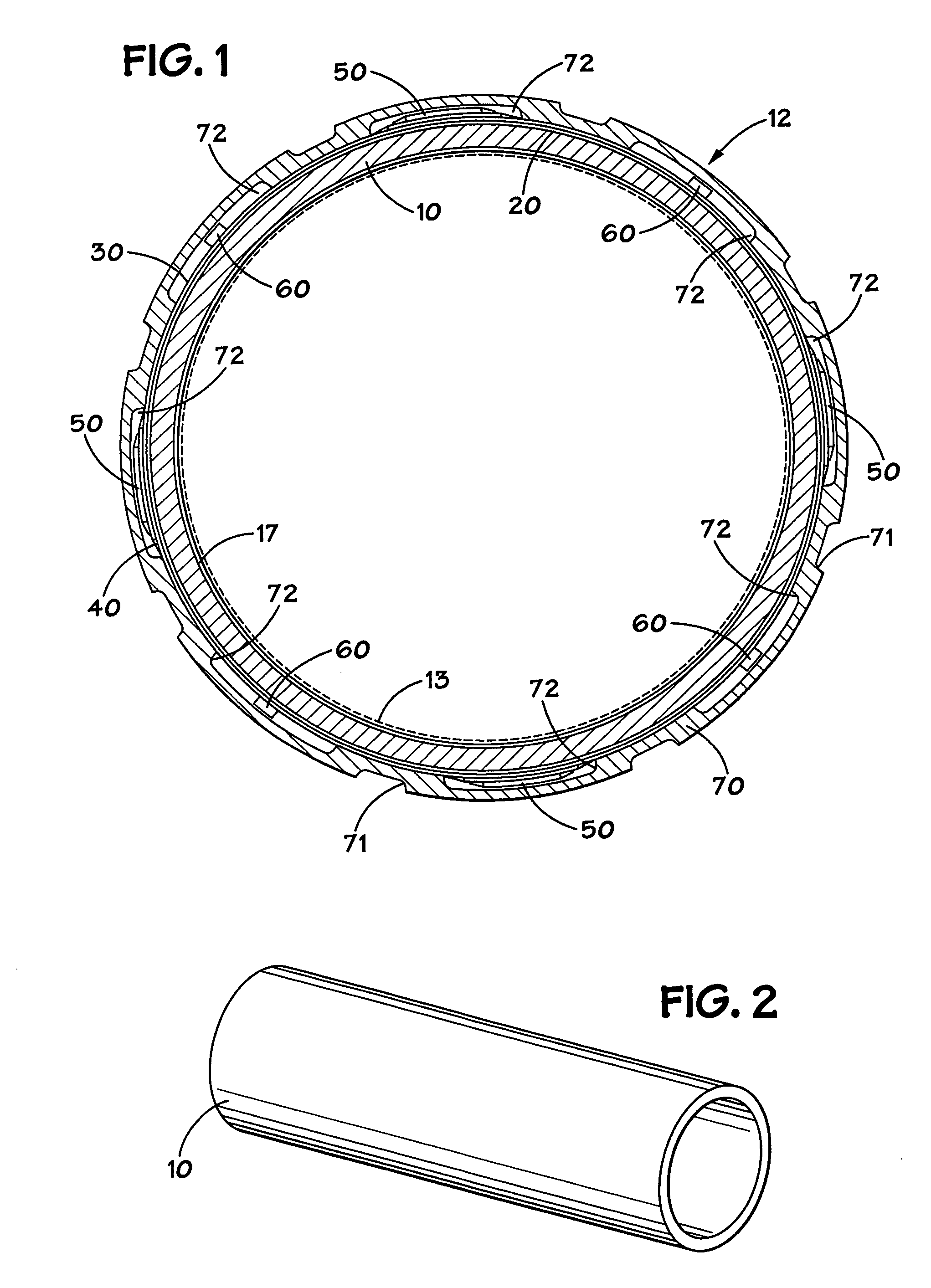
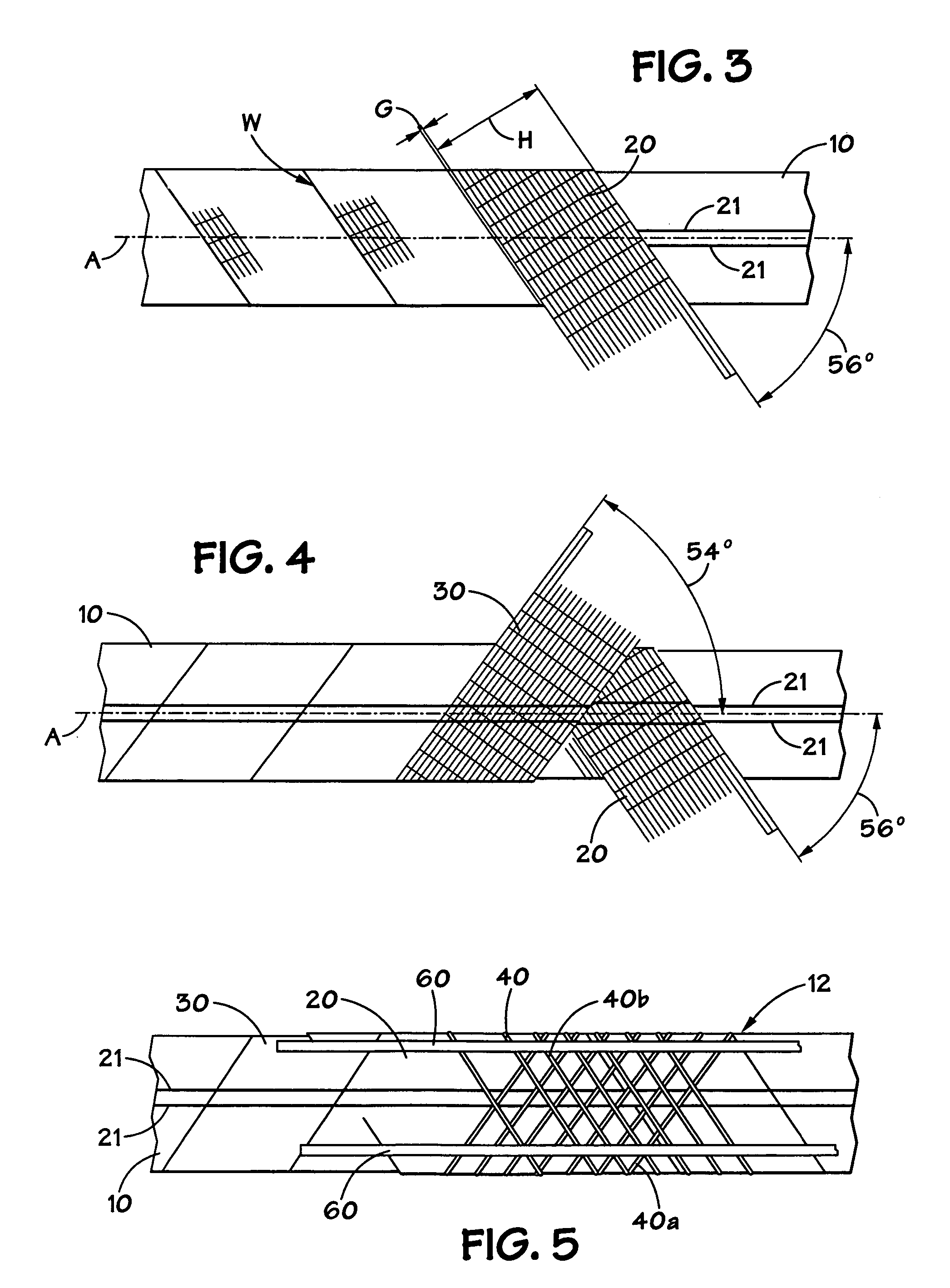
[0083]A pipe liner 12 according to the present invention as shown in FIG. 1 has an innermost first layer 10 (which when formed is a hollow cylinder, in one aspect, a deformable / re-formable cylinder), a second layer 20, a third layer 30, fiber strands 40, spacers 50, fiber optic cables 60, and a cover 70.

[0084]As shown in FIGS. 1 and 2, the first layer 10 is a generally cylindrical member made of flexible material sufficiently strong to support the other layers and components and sufficiently flexible to be compressed, deformed, and re-formed. In one particular aspect the first layer 10 is extruded HDPE (e.g. any suitable grade; e.g. PE 3408, PE 100), with an outside-diameter-to wall-thickness ratio SDR of about 32.5 in hollow cylindrical form. In certain aspects the lined pipe is between 4″ and 30″ in O.D. and, in other aspects, the pipe that is lined is standard size (iron pipe size or IPS) and has an O.D. between 6⅝″ and 16″. In one particular aspect, fifty foot lengths of such fi...


PUM

PropertyMeasurementUnit
pressureaaaaaaaaaa
diameteraaaaaaaaaa
lengthsaaaaaaaaaa

Abstract

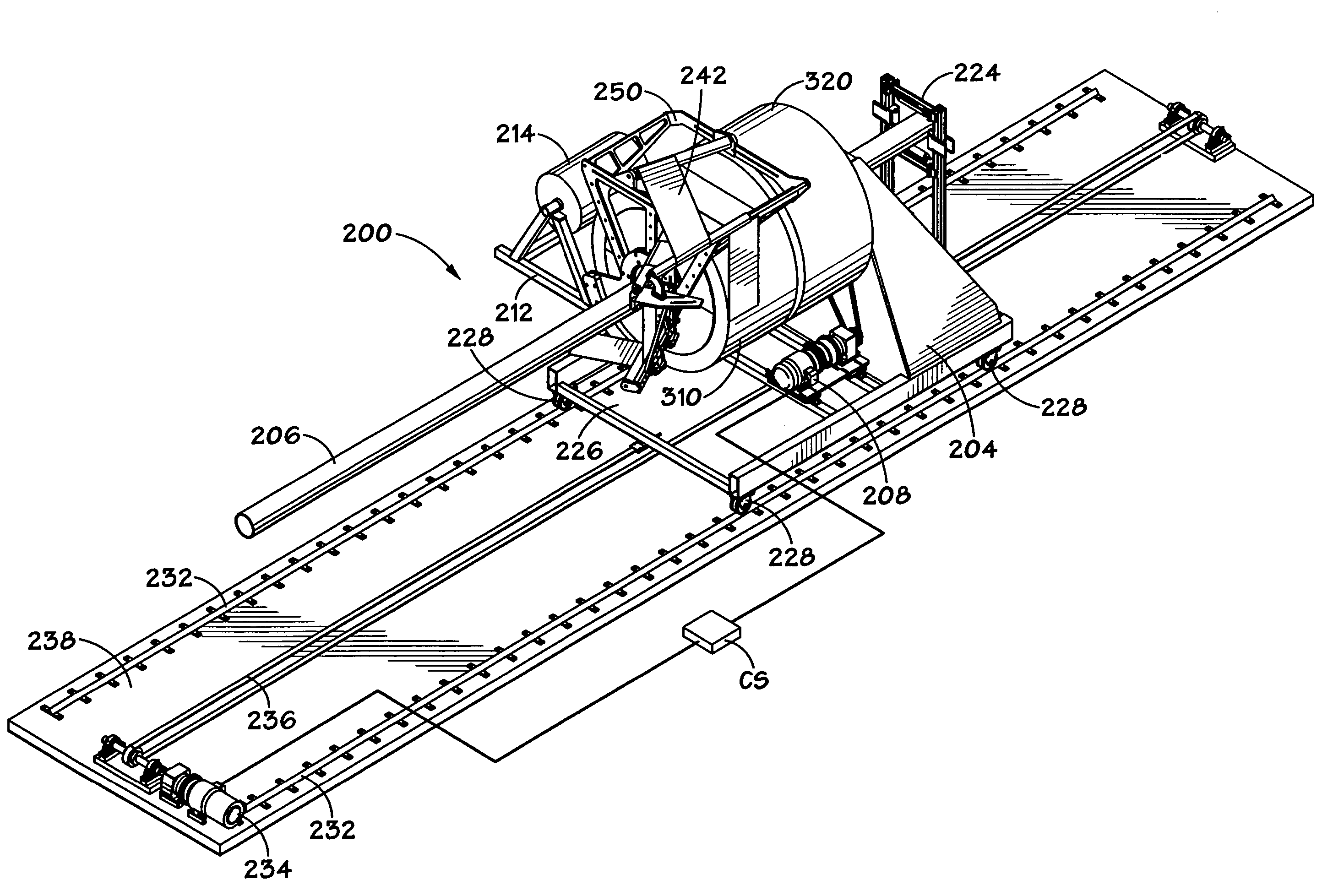
An apparatus for wrapping material onto and around a pipe, the apparatus including a shaft, the shaft rotatable by a driving apparatus, a payout core containing material to be wrapped onto a pipe, the payout core releasably mounted on the shaft, a deflection arm assembly secured to the shaft for rotation by the shaft, rotation of the shaft rotating the deflection arm assembly with respect to the payout core so that the deflection arm assembly takes material from the payout core and wraps the material onto a pipe adjacent the deflection arm assembly, each of the shaft and deflection arm assembly having a central opening through which is movable the pipe as the pipe is being wrapped.

Description

RELATED APPLICATION[0001]This is a continuation-in-part of U.S. application Ser. No. 11 / 033,962 filed Jan. 12, 2005, co-owned with the present invention, fully incorporated herein for all purposes, and with respect to all of which the present invention claims priority under the Patent Laws.BACKGROUND OF THE INVENTION[0002]1. Field of the Invention[0003]The present invention in certain aspects, is directed to systems and methods for making pipe liners, to lined pipe and pipelines, to pipelines with liners and fiber optic sensors, to methods for lining pipe and pipeliners, and, in certain particular aspects, to continuous reinforced thermoplastic pipe liner intended for use as a stand alone pipe liner in the restoration of degraded pipelines.[0004]2. Description of Related Art[0005]Pipeline and / or underground transport of liquids and gases has been utilized for many years. Such pipeline and / or underground transport has proven to be an efficient and safe manner in which to transport po...

Claims


Application Information

Patent Timeline
Patent Type & Authority Patents(United States)
IPC IPC(8): B21C47/02
CPCF16L55/1652F16L55/1656B29C63/105
Inventor GALLAGHER, JAMES L.STRINGFELLOW, WILLIAM D.CHARBONEAU, KENNETH R.CATHA, STEPHEN C.
Owner SMART PIPE COMPANY
Why Eureka
Try Eureka