Method and apparatus for controlled voltage level shifting

a voltage level and switching technology, applied in the direction of electrical equipment, amplifiers, pulse automatic control, etc., can solve the problems of not being able to meet the voltage requirements of all components, the voltage requirements of single power supply may not be able to be met by all components, and the complex system of modern electronic products and devices, so as to increase the control signal and reduce the control signal

Inactive Publication Date: 2008-05-20
MARVELL ISRAEL MISL
View PDF20 Cites 12 Cited by
  • Summary
  • Abstract
  • Description
  • Claims
  • Application Information

AI Technical Summary

Benefits of technology

[0009]The level shifting circuits can each include a serial connection of a MOS transistor, a component such as a resistor, a MOS amplifier, or an electrical connection, and another MOS transistor. One MOS transistor can be connected to an input signal. The other MOS transistor can be connected to the differential amplifier and can receive the control signal from the differential amplifier to provide a level-shifting current that corresponds to the control signal. The level shifting circuit can create a controllable voltage drop by allowing the level-shifting current to flow through the MOS transistors and the component.
[0010]In one aspect of the disclosed invention, a voltage level shifter can perform a first level shifting operation to provide a level-shifted reference signal, provide a control signal to the first level-shifting operation to cause the level-shifted reference signal to substantially match a target signal, and perform a second level-shifting operation based on the control signal to provide a level-shifted version of an input signal. The first level-shifting operation and the second level-shifting operation can occur simultaneously. The voltage level shifter can provide the control signal by comparing the level-shifted reference signal to the target signal. When the level-shifted reference signal is greater than the target signal, the voltage level shifter can increase the control signal. When the level-shifted reference signal is less than the target signal, the voltage level shifter can decrease the control signal.

Problems solved by technology

Modern electronic products and devices are complex systems that include many sub-systems.
Even with these standards, however, it can still be a challenge to satisfy the various requirements of different components.
A single power supply may not be able to accommodate the voltage requirements of all of the various sub-systems.
However, an analog implementation may suffer from sensitivities to undesirable operating or environmental conditions, such as temperature variations and / or power supply noise, for example.

Method used


Image

  • Method and apparatus for controlled voltage level shifting
  • Method and apparatus for controlled voltage level shifting
  • Method and apparatus for controlled voltage level shifting

Examples


Embodiment Construction

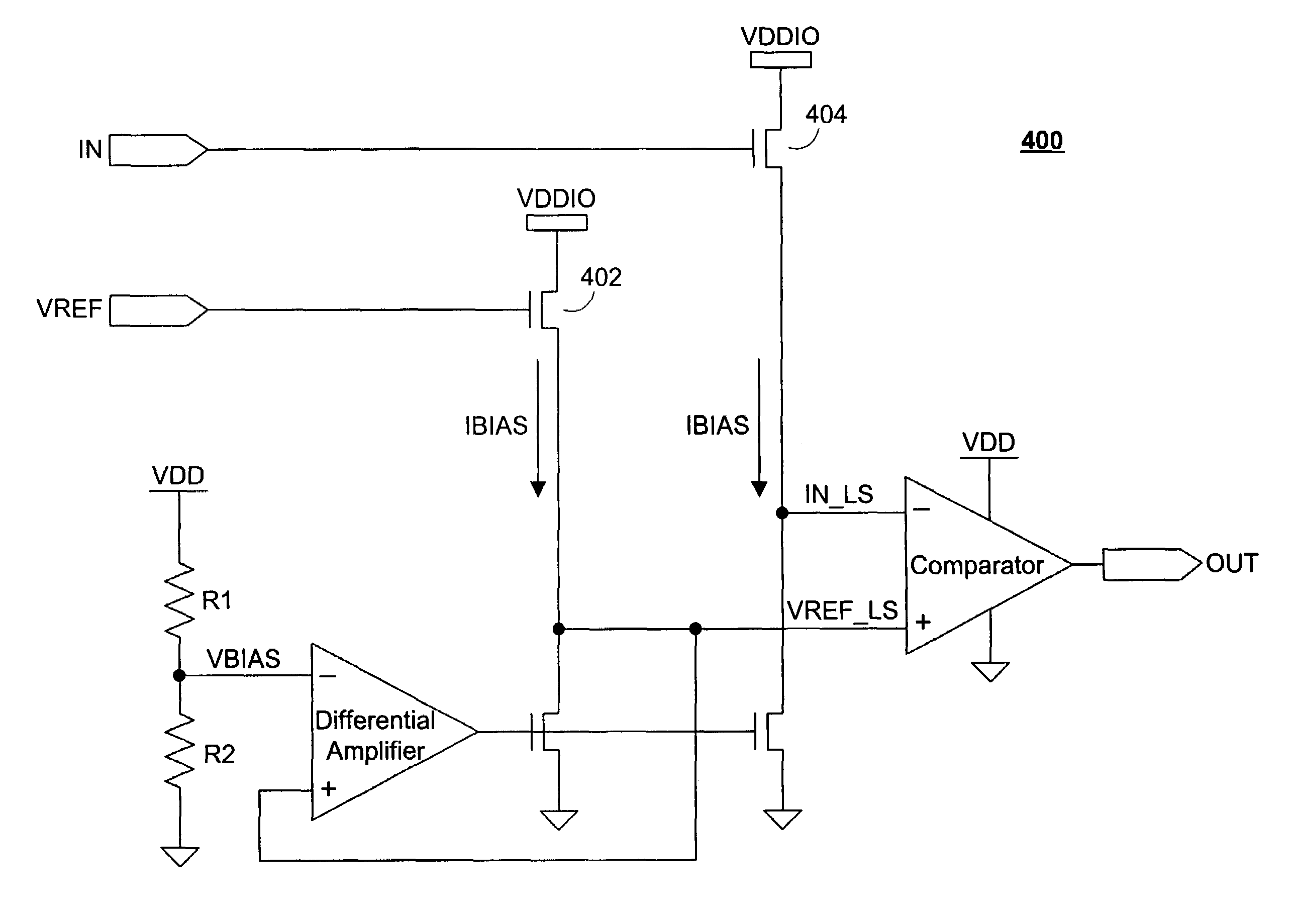
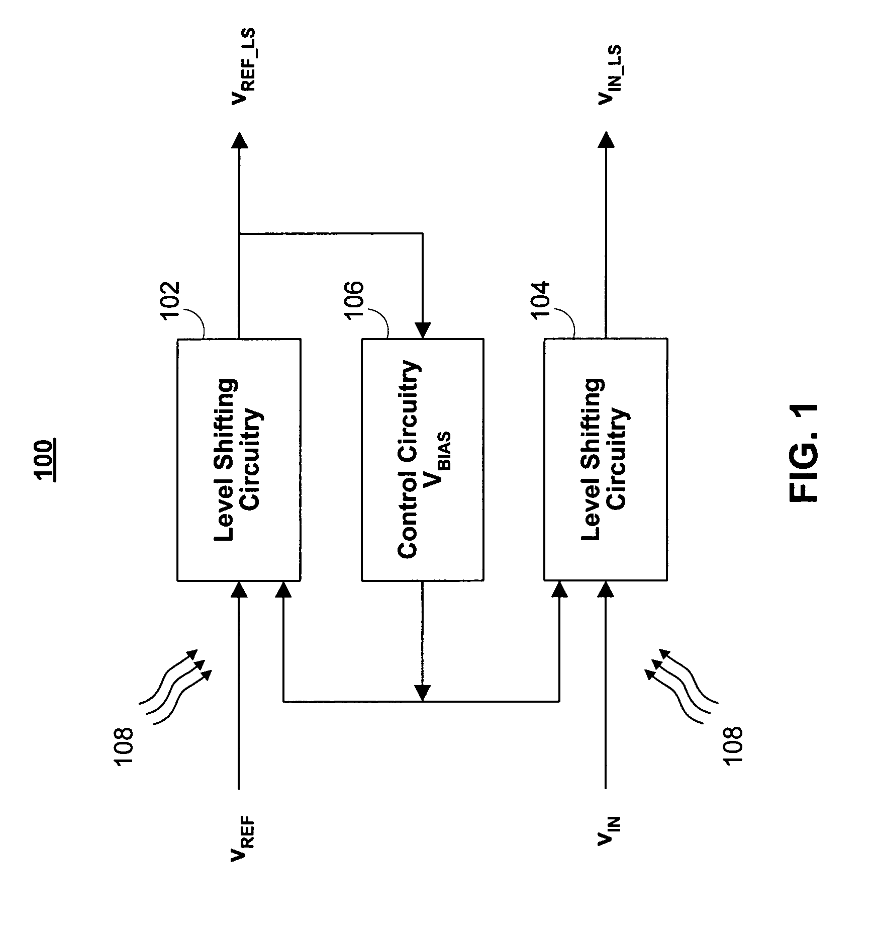
[0027]In accordance with aspects of the disclosed invention, FIG. 1 shows a block diagram of an exemplary voltage level shifter 100. The voltage level shifter 100 receives a reference signal VREF and an input signal vIN, which may originate from another circuit, device, or system. In one embodiment, the voltage level shifter 100 can be configured to receive a reference signal vREF that is a constant voltage signal. The input signal vIN can have a defined voltage swing, and the reference signal vREF can be the midpoint voltage between the swing levels. In another embodiment, the voltage level shifter 100 can be configured to receive a reference voltage vREF that is a varying signal.

[0028]The illustrated voltage level shifter 100 includes two level shifting circuits 102,104. The first level shifting circuit 102 receives the reference signal vREF and performs a level shifting operation to provide a level-shifted reference signal vREF—LS. The second level shifting circuit 104 receives t...


PUM


Abstract

A method and an apparatus for voltage level shifting are described. A voltage level shifter includes two level shifting circuits and a differential amplifier. The differential amplifier forms a feedback loop with one level shifting circuit. The feedback loop controls the level shifting operation of both level shifting circuits. The differential amplifier can operate to provide a control signal that causes a level-shifted signal in the feedback loop to match a target signal. The two level shifting circuits can perform their level shifting operation based on the control signal.

Description

CROSS-REFERENCE TO RELATED APPLICATIONS[0001]This application claims the benefit under 35 U.S.C. §119(e) of U.S. Provisional Application No. 60 / 653,221, filed Feb. 14, 2005, which is incorporated herein by reference in its entirety.BACKGROUND OF THE INVENTION[0002]This invention relates to voltage level shifting, and more particularly to controlled voltage level shifting that is operable over various operating and environmental conditions.[0003]Modern electronic products and devices are complex systems that include many sub-systems. For example, a computer system can include disk drives, random access memory, and graphics hardware, among other things. To facilitate integration and compatibility of different electronic components, industry standards organizations typically adopt operating and manufacturing standards for electronic components. Even with these standards, however, it can still be a challenge to satisfy the various requirements of different components.[0004]Operating sta...

Claims


Application Information

Patent Timeline
Patent Type & Authority Patents(United States)
IPC IPC(8): H03L5/00
CPCH03F3/45475H03F2203/45101H03F2203/45136
Inventor BAZES, MEL
Owner MARVELL ISRAEL MISL
Why Eureka
Try Eureka