Method and device for driving an image display apparatus

a technology of image display and drive device, which is applied in the direction of instruments, computing, electric digital data processing, etc., can solve the problems of limited reserve and more energy consumption of boosting, and achieve the effects of brighter images, increased display control signals, and temporary boosting of backligh

Active Publication Date: 2009-05-07
TOP VICTORY INVESTMENTS
View PDF6 Cites 4 Cited by
  • Summary
  • Abstract
  • Description
  • Claims
  • Application Information

AI Technical Summary

Benefits of technology

[0016]The present invention proposes a method for driving an image display device using backlight dimming and backlight boosting such that, on average, the power consumed by the backlight does not exceed a predetermined power rating. In darker scenes, the backlight is dimmed and the display control signals are increased. In very bright scenes, the backlight can temporarily be boosted.
[0017]The predetermined power setting may be equal to the nominal power setting; in that case, brighter images are achieved. However, the predetermined power setting may also be lower than the nominal power setting; in that case, an overall power saving for the display apparatus is achieved.
[0018]Backlight dimming saves energy, but backlight boosting spends more energy. In order not to exceed the predetermined average, it is only possible to perform backlight boosting if it is preceded by a period of backlight dimming. It might be said that backlight dimming provides an energy reserve that can be consumed to perform backlight boosting. However, such reserve is limited. The present invention provides a method for backlight boosting which uses the energy reserve in an efficient manner and, when the energy reserve gets exhausted, reduces the excess energy consumption in an effective manner.

Problems solved by technology

Backlight dimming saves energy, but backlight boosting spends more energy.
However, such reserve is limited.

Method used


Image

  • Method and device for driving an image display apparatus
  • Method and device for driving an image display apparatus
  • Method and device for driving an image display apparatus

Examples


Embodiment Construction

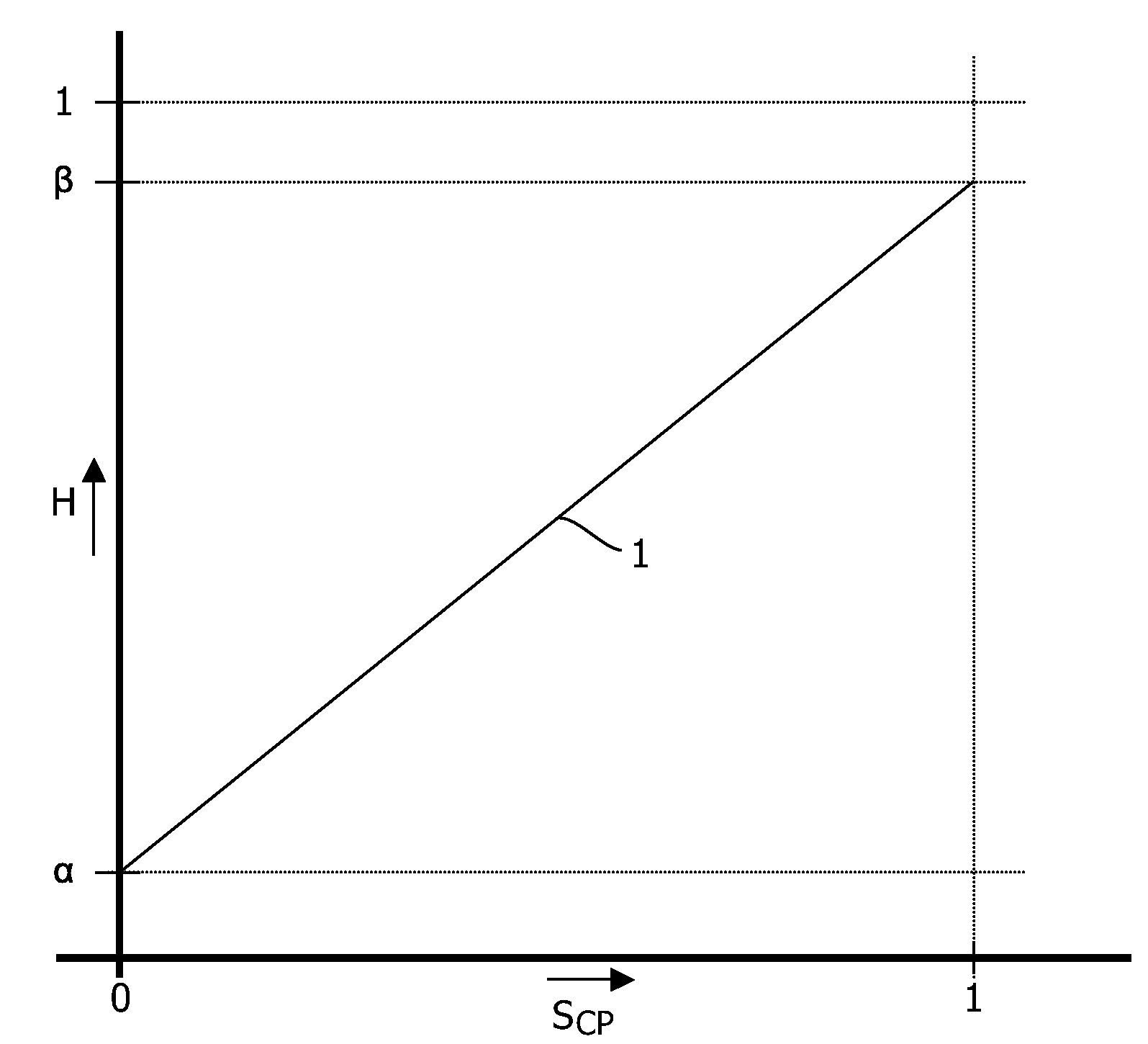
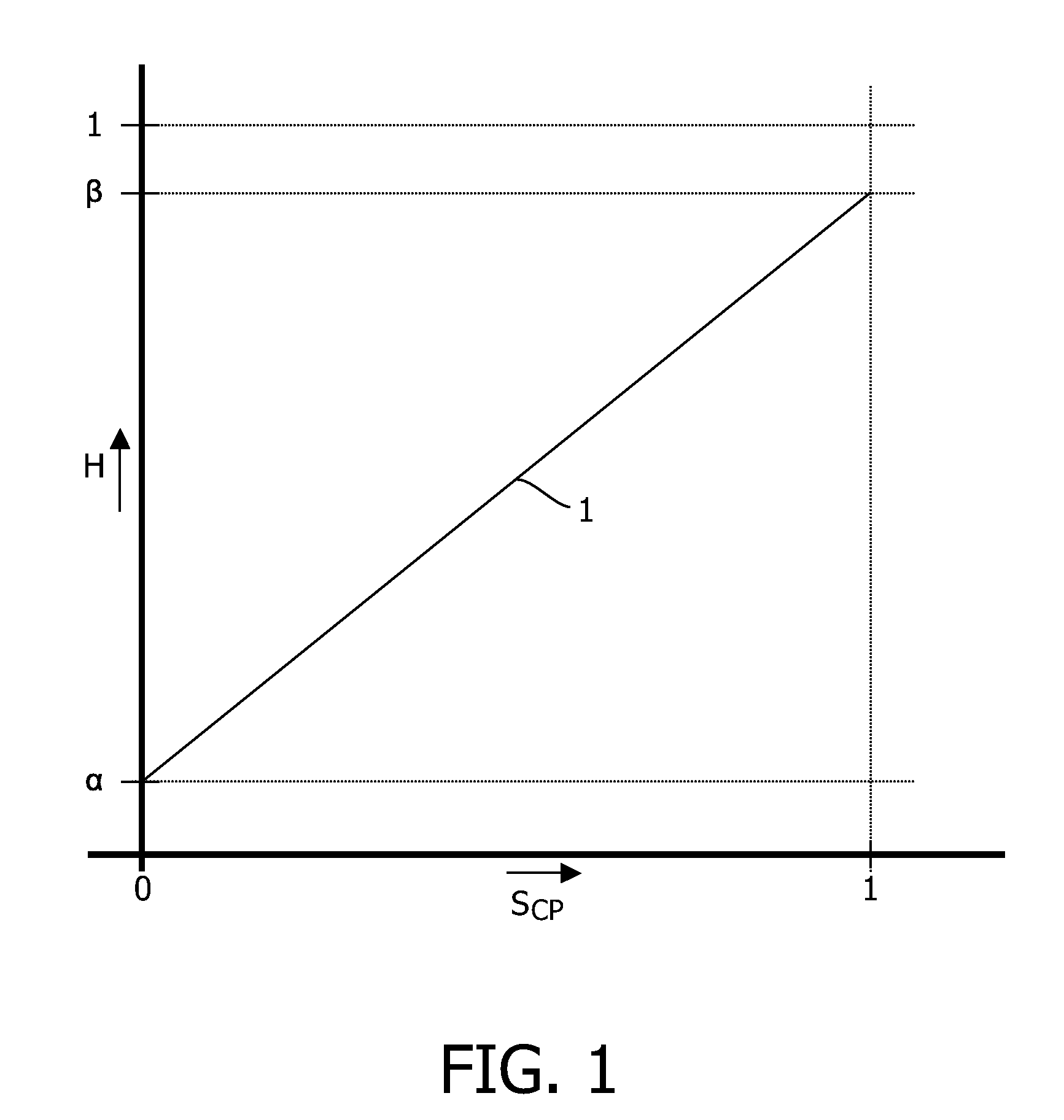
[0025]FIG. 1 is a graph schematically illustrating a transmission characteristic of a pixel, for instance an LCD cell. The horizontal axis represents a control signal SCP, ranging from 0 for minimum transmission to 1 for maximum transmission. The vertical axis represents a transmission ratio H of the pixel, ranging from 0 for perfectly blocking to 1 for 100% transmission. Line 1 shows that for control signal SCP=0, the transmission ratio H(0)=α>0, indicating that the minimum transmission of a pixel is always somewhat larger than zero. Further, line 1 shows that for control signal SCP=1, the transmission ratio H(1)=β1 is shown as a straight line, but this is not essential.

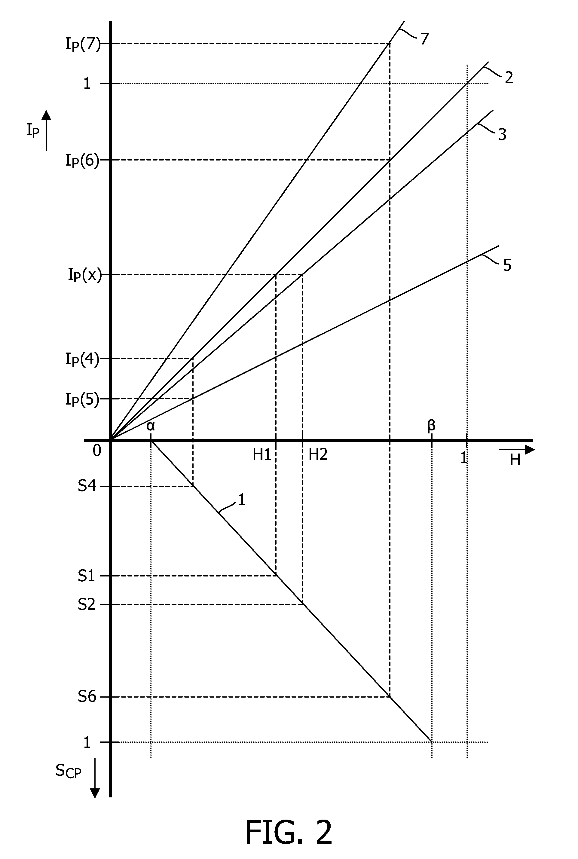
[0026]FIG. 2 is a graph schematically illustrating backlight dimming. The vertical axis downwards represents the control signal SCP, and the horizontal axis represents the transmission ratio H of the pixel, so that quadrant IV of this graph corresponds to the graph of FIG. 1. The vertical axis upwards represents the...


PUM


Abstract

A method for driving an image display device (110) comprising at least one backlight lamp (111) and a display screen (112) is described. The method comprises the steps of:
    • receiving an image data signal (D);
on the basis of the image data signal (D), calculating a content-related backlight control signal (SCL(D)) for the backlight lamp (111) for setting the intensity of the backlight;
  • generating an average signal (SAV) that represents a time-average of the power consumed by the backlight lamp (111);
  • comparing the average signal (SAV) with a reference signal (SREF);
  • on the basis of the calculated content-related backlight control signal (SCL(D)), taking into account the result of the said comparison, generating an actual backlight control signal (SCL(A)) for the backlight lamp (111).

    Description

    FIELD OF THE INVENTION[0001]The present invention relates in general to a method and device for driving an image display apparatus, such as for instance in a television, a monitor, etc.[0002]In general, the invention can be applied to several types of image display apparatus having a backlight. In the following, the invention will be described for an image display device of the LCD type, but it is to be noted that it is not intended to restrict the invention to LCD image display devices.BACKGROUND OF THE INVENTION[0003]In an image display device, an image consists of a large number of image points, each having a specific grey value or color and a specific brightness. In a specific class of image display devices, a viewer is watching a display screen behind which a light source is arranged, the so-called backlight. The display screen comprises a plurality of pixels which can be controlled to pass light or to block light. In a specific embodiment, a pixel is implemented as a liquid cr...

    Claims


    Application Information

    Patent Timeline
    Patent Type & Authority Applications(United States)
    IPC IPC(8): G09G5/00G09G3/34
    CPCG09G3/3406G09G2360/16G09G2330/021G09G2320/0646G02F1/133G09G3/34G09G3/36
    Inventor STESSEN, JEROEN HUBERT CHRISTOFFEL JACOBUSVAN MOURIK, JOHANNES GERARDUS RIJK
    Owner TOP VICTORY INVESTMENTS
    Why Eureka
    Try Eureka