Apparatus for and method of driving X-Y scanner in scanning probe microscope

Inactive Publication Date: 2007-01-18
PARK SYST CORP
View PDF3 Cites 2 Cited by
  • Summary
  • Abstract
  • Description
  • Claims
  • Application Information

AI Technical Summary

Benefits of technology

[0024] According to another aspect of the invention, there is provided a method of driving an X-Y scanner in a scanning probe microscope. The method comprises steps of: (a) outputting a control signal for controlling a plurality of drivers such that a mobile stage can be moved along an x- and y-axis; (b) detecting a current-position signal of the mobile stage using a position detector for detecting a position of mobile stage; (c) analyzing the current-position signal from the position detector and determining whether the mobile stage is moved by a same quantity of distance from a reference position of each axis to a desired position along the positive or negative direction thereof; and (d) controlling as to whether or not each driver is to be operated, depending on the determination.
[0025] In the above step (c), if the mobile stage is not moved th

Problems solved by technology

An optical microscope has a limitation in its resolving power due to the diffraction of light, called a diffraction limitation.
However, the scanning probe microscope has a high resolution, which is not achievable in the common-type optical microscopes.
A contact-type scanning probe microscope may damage the surface of specimen due to contact of the probe with the surface.
In addition, in order for the corner of wafer to be moved into the center of the scanner, the size of the sample chuck, where the wafer is held, must be inevitably enlarged.
In the above conventional scanner, if the two drivers installed at each axis do not have a balanced characteristic of voltage-distance, a clear image cannot be easily acquired, with respect to the peripheral area of sample.
Thus, the expanded distance of each driver varies depending on the applied voltages, so that a parasitic motion such as tilting or rotation occurs in the peripheral area of sample, thereby failing to perform a precision control.

Method used


Image

  • Apparatus for and method of driving X-Y scanner in scanning probe microscope
  • Apparatus for and method of driving X-Y scanner in scanning probe microscope
  • Apparatus for and method of driving X-Y scanner in scanning probe microscope

Examples


first embodiment

[0066]FIGS. 6a and 6b are schematic circuit diagrams showing a signal controller of the X-Y scanner in the SPM according to the invention. Specifically, FIG. 6a is a schematic circuit diagram for the x-axis signal controller, and FIG. 6b is a schematic circuit diagram for the y-axis signal controller.

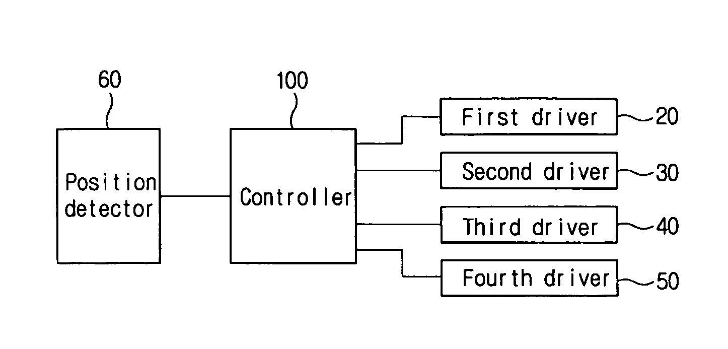
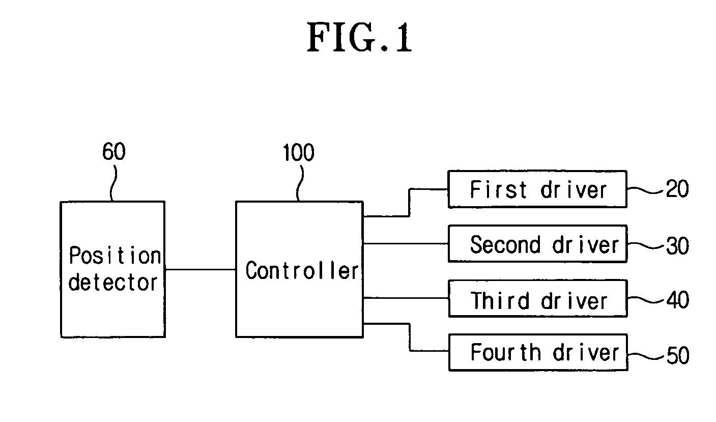
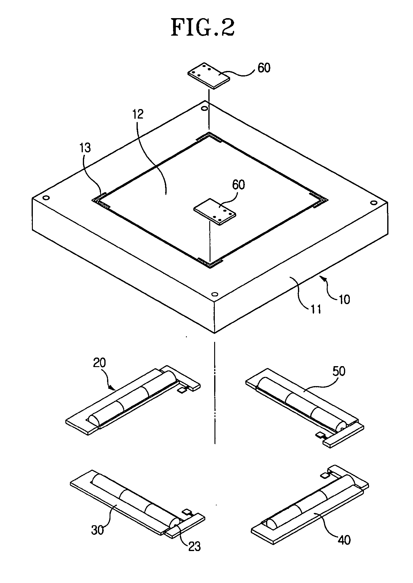
[0067] In FIG. 6a, reference numeral V1 denotes a control signal (voltage) to be applied to an x-axis sub driver Y1 and an x-axis main driver Y2. More specifically, the position detector 60 (in FIG. 2) detects the current x-axis position of the mobile stage 12 (in FIG. 2), which is displaced from an x-axis reference position, and then outputs a position signal. Based on the position signal (voltage value), the controller (hereinafter, referred to as a “voltage controller”) calculates a control signal (voltage) V1 in order to move the mobile stage to a desired position. Reference numeral 110 denotes a first voltage divider. The first voltage divider 110 compares the differences in the to...

second embodiment

[0114]FIG. 9a is a flow chart explaining the operation of the local feedback unit in the invention shown in FIGS. 8a and 8b. FIG. 9b is a detailed flow chart of the portion A in FIG. 9a and FIG. 9c is s detailed flow chart of the portion B in FIG. 9a.

[0115] Referring to FIG. 9a, first, the voltage controller generates an x-axis control signal V1 and an y-axis control signal V2 (S30), and determines whether the X-Y scanner is on or off (S31).

[0116] At step S31, if the X-Y scanner is on, the portion A of FIG. 9b is executed. That is, at step S41, the position detector 60 detects a moved-position of the mobile stage, and, at step S42, a control signal to be applied to the driver is calculated, based on the detected moved-position signal.

[0117] At step S32, the generated control signals are amplified to a high voltage, and at step S33, the amplified signals are applied to the respective drivers to thereby drive each driver.

[0118] Then, the local feedback controller is determined as ...

third embodiment

[0125]FIGS. 10a to 10d are a schematic circuit diagram showing a local feedback unit of the X-Y scanner in the SPM according to the invention. Specifically, FIG. 10a is a schematic circuit diagram of an x-axis feedback unit for the x-axis sub driver, FIG. 10b is a schematic circuit diagram of an x-axis feedback unit for the x-axis main driver, FIG. 10c is a schematic circuit diagram of a y-axis feedback unit for the y-axis sub driver, and FIG. 10d is a schematic circuit diagram of a y-axis feedback unit for the y-axis main driver.

[0126] In FIGS. 10a to 10d, the same elements as in previous embodiments are denoted by the same reference numerals and detains thereon will not be repeated here.

[0127] In FIG. 10a, reference numeral 130 denotes an x-axis feedback unit of x-axis sub driver, which compares the moving distances of the mobile stage 12 driven by the x-axis sub driver Y1 and applies a differential signal (voltage), corresponding to a difference in the moving distances, to both ...


PUM


Abstract

Disclosed is an apparatus for driving an X-Y scanner in a scanning probe microscope. The apparatus includes one or more position detector for detecting a moved-position of a mobile stage and generating a moved-position signal. Thee mobile stage is capable of holding a specimen and moving along at least one of x-axis and y-axis from a reference position. A controller is provided for generating a plurality of control signals based on the moved-position signal from the position detector, such that the mobile stage is moved along at least one of x-axis and y-axis by a certain desired quantity of distance. Also, a plurality of drivers is provided for moving the mobile stage along at least one of x-axis and y-axis, in response to the control signals from the controller.

Description

BACKGROUND OF THE INVENTION [0001] 1. Field of the Invention [0002] The present invention relates to an apparatus for and a method of driving an X-Y scanner in a scanning probe microscope. More specifically, the invention relates to an operation of X-Y scanner, in which plural drivers having different voltage-distance characteristics can be controlled such that a mobile stage can be moved in an identical and consistent manner. [0003] 2. Background of the Related Art [0004] A scanning probe microscope (SPM) is used for examining a nano-scaled specimen or sample. In the SPM, while a pointed probe moves in a canning fashion above the specimen to be observed or examined, the surface contour and other physical properties thereof are observed and measured. [0005] The scanning probe microscope includes a scanning tunnel microscope (STM), an atomic force microscopy (AFM), a near field scanning optical microscope (NSOM), a magnetic force microscope (MFM), or the like. An optical microscope h...

Claims


Application Information

Patent Timeline
IPC IPC(8): H01J5/16
CPCG01Q10/04B82Y35/00
Inventor KIM, JOONHUIPARK, SANG-IL
Owner PARK SYST CORP
Why Eureka
Try Eureka