Hardware curve flattening of crystal oscillator temperature drift followed by software compensation for residual offset

a technology of crystal oscillator and software compensation, applied in the field of satellite receivers, can solve the problems of significant frequency error, local reference oscillator crystal error, frequency error in gps receiver, etc., and achieve the effect of accurate computation of offset, improved time required to produce, and flat temperature respons

Inactive Publication Date: 2008-05-20
FURUNO ELECTRIC CO LTD +1
View PDF3 Cites 39 Cited by
  • Summary
  • Abstract
  • Description
  • Claims
  • Application Information

AI Technical Summary

Benefits of technology

[0008]Briefly, a method embodiment of the present invention providing for the correcting of frequency errors in a local reference frequency crystal oscillator of a GPS receiver begins with a step in which the ordinary temperature response of a crystal is characterized. A hardware circuit is incorporated with that crystal to mirror that same characteristic. A temperature sensor is used to control a compensation applied. The combination outputs a fairly flat temperature response, e.g., near zero delta-frequency change over the operating temperature range. But this flat response has an unknown offset from the true frequency. A next step finds a precision timing reference, such as when the

Problems solved by technology

Crystals are particularly sensitive to their operating temperatures, so temperature variations cause a major source of frequency error in GPS receivers.
Relatively large frequency uncertainties can result from local reference oscillator crystal errors.
Prior art GPS receivers have resorted to using highly accurate crystals, but these can be very costly.
Since manufacturing cost is tolerance-dependent, it is best not to specify a wider operating temperatu

Method used


Image

  • Hardware curve flattening of crystal oscillator temperature drift followed by software compensation for residual offset
  • Hardware curve flattening of crystal oscillator temperature drift followed by software compensation for residual offset
  • Hardware curve flattening of crystal oscillator temperature drift followed by software compensation for residual offset

Examples


Embodiment Construction

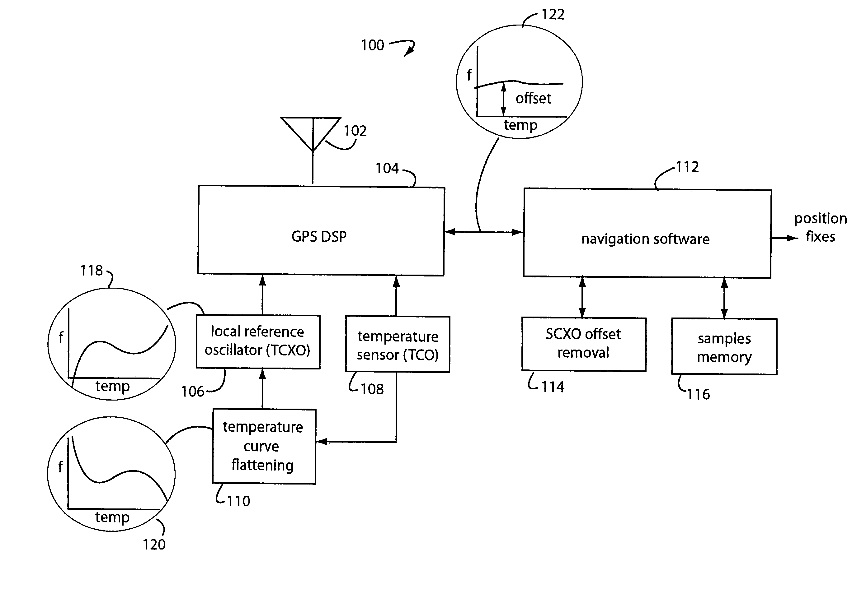
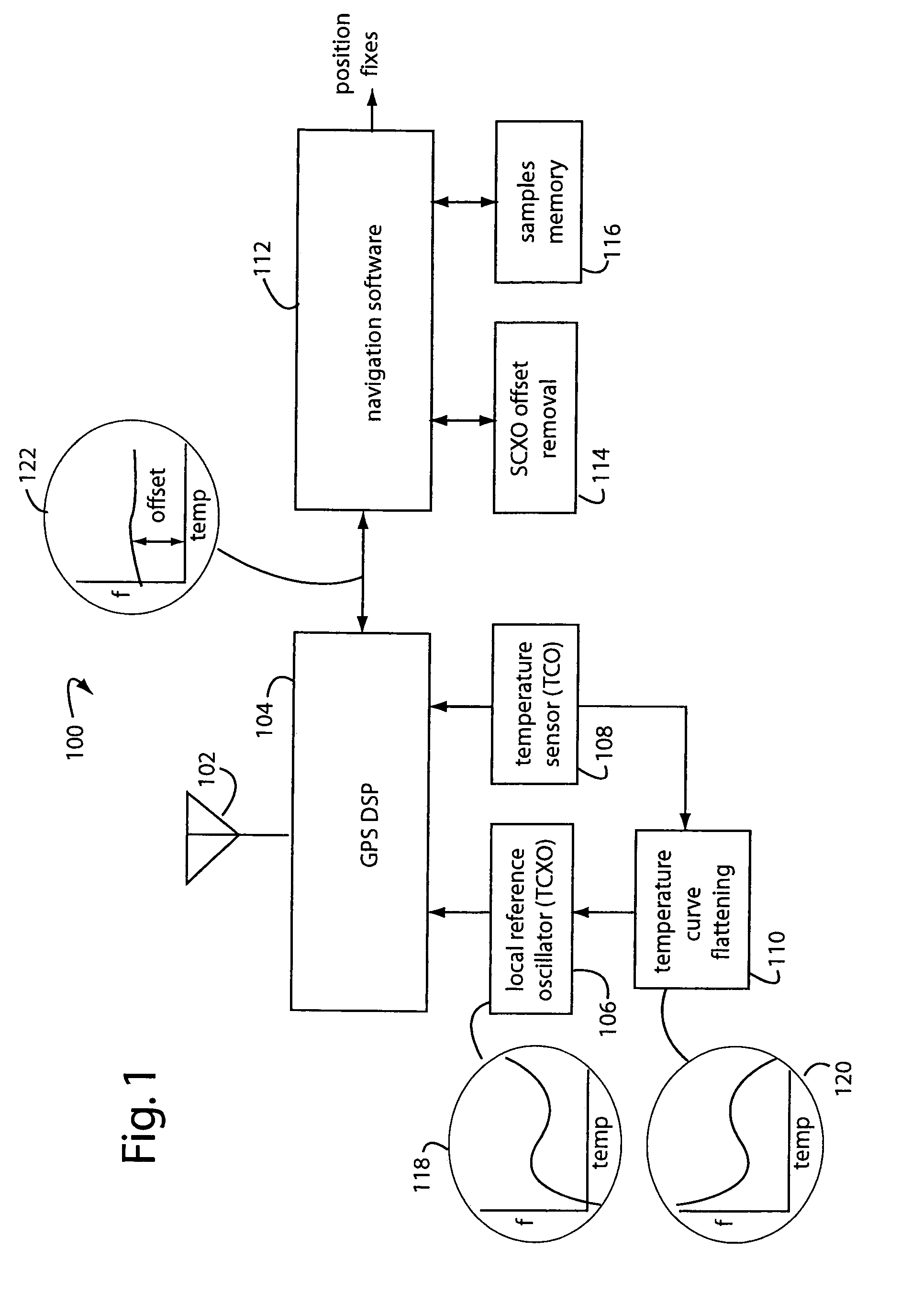
[0015]FIG. 1 illustrates a GPS receiver embodiment of the present invention, and is referred to herein by the general reference numeral 100. The GPS receiver 100 comprises an antenna 102 to receive the microwave transmissions of orbiting GPS satellites, and a GPS RF and digital signal processor (RF-DSP) 104 to tune and demodulate these signals. A local reference oscillator 106 includes a temperature compensated crystal oscillator (TCXO). Its temperature is measured by a temperature sensor 108, e.g., a temperature controlled oscillator (TCO) that outputs a frequency proportional to environmental temperature. A hardware implemented circuit 110 is used to frequency compensate the TCXO 106 by flattening out its characteristic curve. It operates by generating an opposite temperature characteristic to that expected for the particular TCXO being used or its manufacturers specifications. During manufacture of the receiver 100, it is critical that this circuit need no further adjustment.

[001...


PUM


Abstract

A method for correcting frequency errors in the local reference frequency crystal oscillator of a GPS receiver begins with a step in which the ordinary temperature response of a crystal is characterized. A hardware circuit is incorporated with that crystal to mirror that same characteristic. A temperature sensor is used to control a compensation applied. The combination outputs a fairly flat temperature response, e.g., near zero delta-frequency change over the operating temperature range. But this flat response has an unknown offset from the true frequency. A next step finds a precision timing reference, such as when the receiver locks onto and tracks GPS satellites. The receiver then knows time precisely and a navigation software can compute the offset accurately. A value is stored for that offset in memory. Such value is thereafter recalled at each cold start and is used by software to remove the expected frequency offset.

Description

FIELD OF THE INVENTION[0001]The present invention relates to navigation satellite receivers, and more particularly to methods and systems for improving the time-to-first-fix (TTFF) by reducing the frequency uncertainty associated with local crystal oscillators.DESCRIPTION OF THE PRIOR ART[0002]Commercial oscillator crystals are available with frequency stabilities on the order of one-part-per-million (1-ppm) to 100-ppm. In the past, this was considered good in most receiver local oscillator applications. But global positioning system (GPS) receivers need local reference oscillator frequency stabilities that are much better then 1-ppm. Crystals are particularly sensitive to their operating temperatures, so temperature variations cause a major source of frequency error in GPS receivers.[0003]When a GPS receiver comes up from a cold start, it must begin a frequency search to find GPS satellite transmissions. Relatively large frequency uncertainties can result from local reference oscil...

Claims


Application Information

Patent Timeline
IPC IPC(8): G01S1/00G01S19/23
CPCG01S19/235H03J1/005H03L1/026H03L7/18
Inventor WOO, ARTHUR N.
Owner FURUNO ELECTRIC CO LTD
Why Eureka
Try Eureka