
Coherent combining/noncoherent detection (CCND) method and apparatus for detecting a pilot signal in a wireless communication system

a wireless communication system and coherent combination technology, applied in the field of coherent combining/non-coherent detection (ccnd), can solve the problems of reducing detection performance and largely limited trade-offs, and achieve faster search times, more reliable detections, and improved signal-to-noise ratio.

Active Publication Date: 2013-02-19
AVAGO TECH INT SALES PTE LTD
View PDF15 Cites 2 Cited by
  • Summary
  • Abstract
  • Description
  • Claims
  • Application Information

AI Technical Summary

Benefits of technology

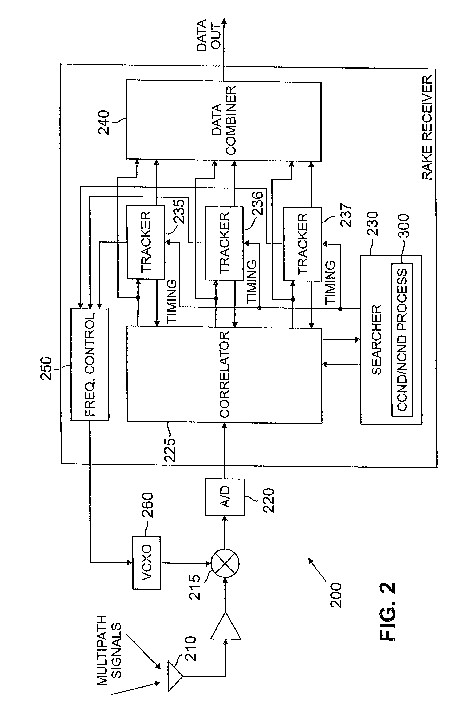
The present invention is about improving the signal-to-noise ratio (SNR) in a communication system by combining coherent and noncoherent detection techniques. By locking the receiver's frequency and measuring the residue frequency error over several correlator outputs, the technique reduces the phase dependency and improves the SNR by 2.5 dB over conventional noncoherent combining / noncoherent detection techniques. This results in faster search times, more reliable detections, and additional power savings. The invention also addresses the case where the accumulation length is too large and coherent combining over L correlator outputs will have significant degradation. In this case, the L outputs can be broken into M groups each of which contain L1 outputs to prevent cancellation of a peak due to a rotating pilot signal.

Problems solved by technology

Such requirements, however, are mutually exclusive and trade-offs are required.
The trade-offs are largely limited, however, by the complicated and time-intensive noncoherent combining / noncoherent detection (NCND) scheme that is employed in current system designs.
In addition, the noncoherent combining severely degrades the detection performance.

Method used


Image

  • Coherent combining/noncoherent detection (CCND) method and apparatus for detecting a pilot signal in a wireless communication system
  • Coherent combining/noncoherent detection (CCND) method and apparatus for detecting a pilot signal in a wireless communication system
  • Coherent combining/noncoherent detection (CCND) method and apparatus for detecting a pilot signal in a wireless communication system

Examples


Embodiment Construction

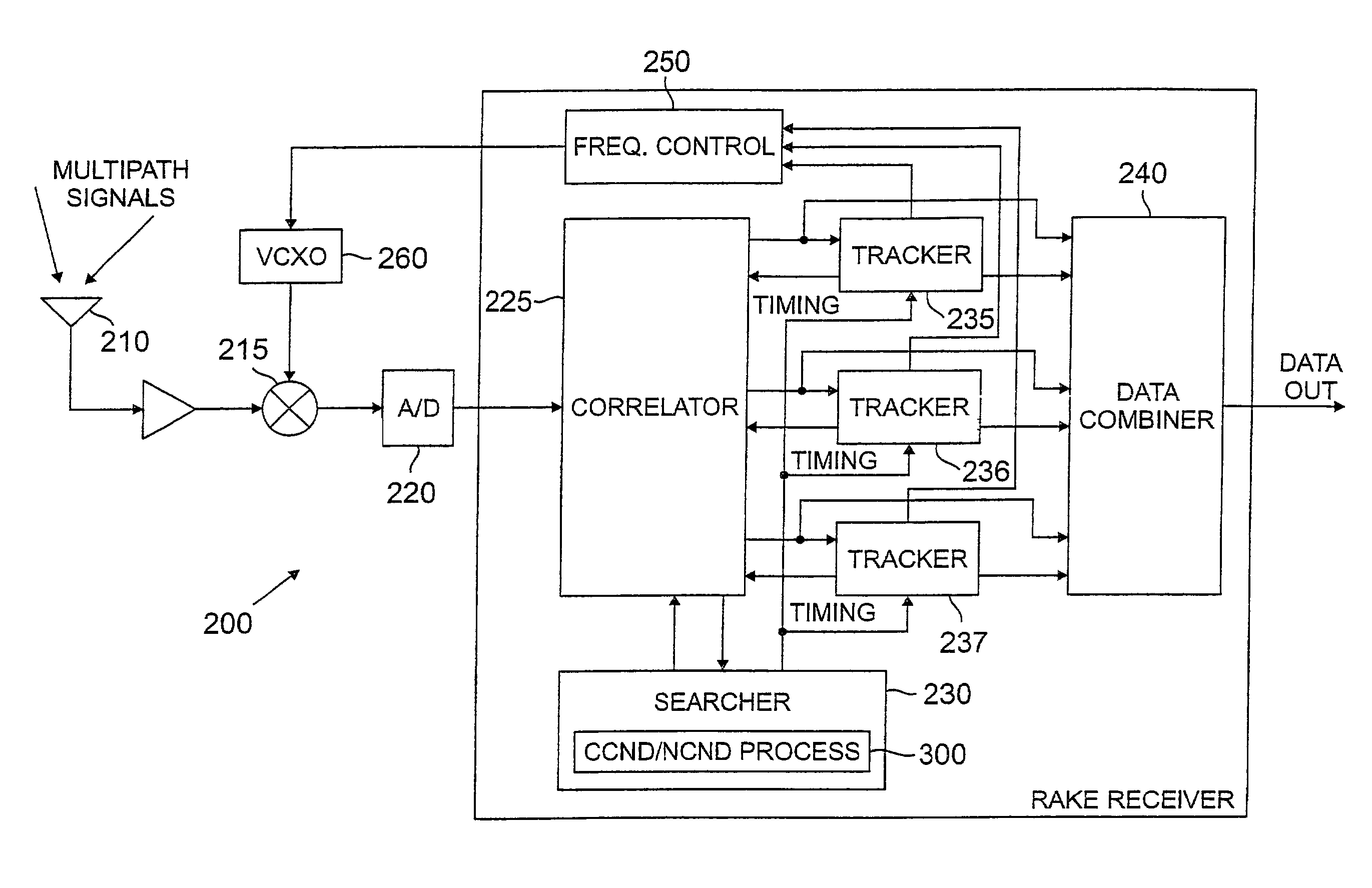
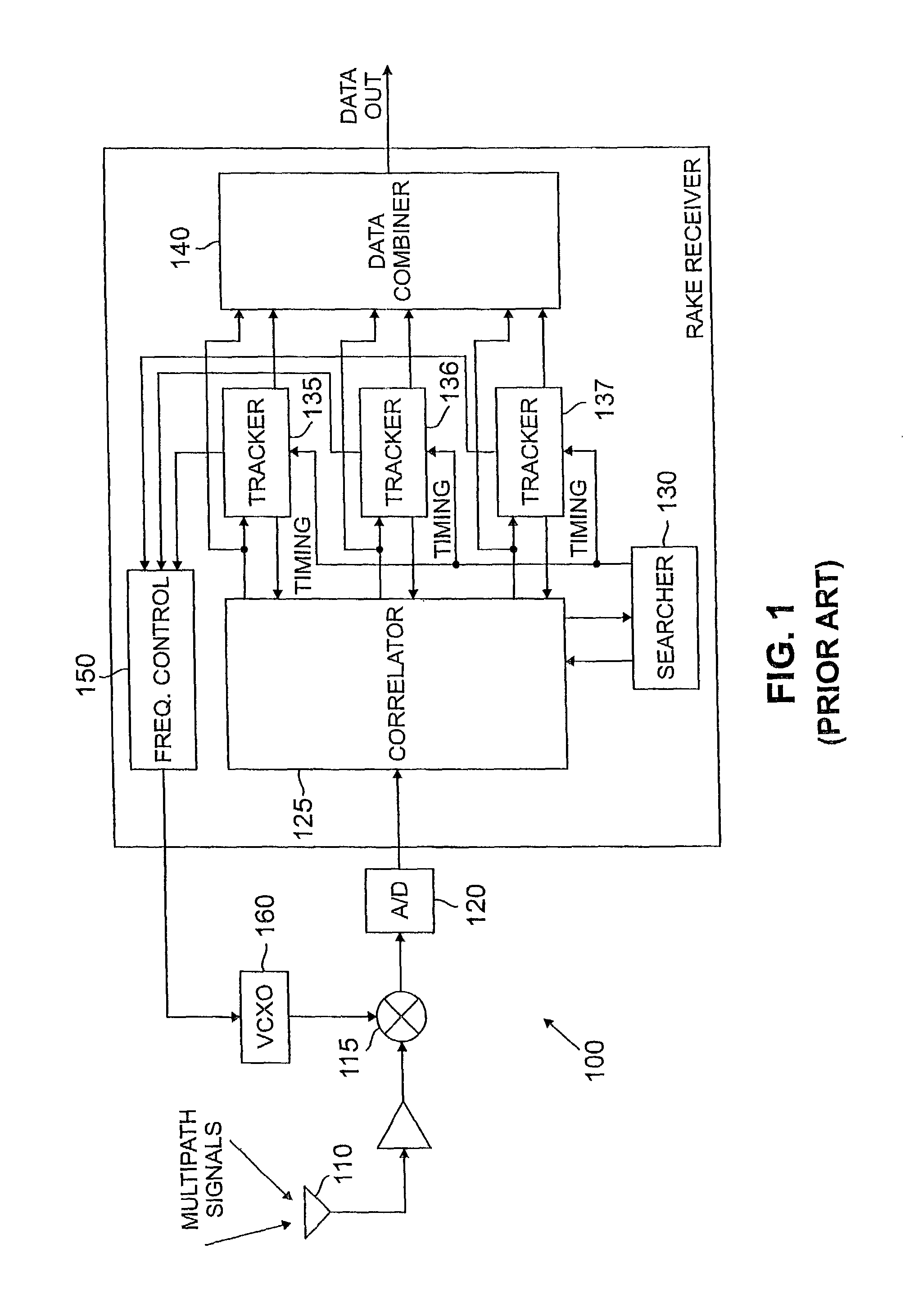
[0014]FIG. 1 illustrates a representative receiver 100 that implements conventional noncoherent combining / noncoherent detection techniques. As shown in FIG. 1, the multi-path (and multi-channel) signals are received by an antenna 110, returned to baseband by a mixer 115 that multiplies the received signal by the carrier frequency, and sampled by an analog-to-digital converter 120.

[0015]It is noted that when the receiver 100 initially searches for the pilot channel, the frequency and phase of the incoming signal are unknown. When the incoming signal becomes aligned with the PN sequence inputs to the correlator 125, there will be a peak at the output of the correlator 125. The searcher 130 monitors the output of the correlator 125 for such peaks. The operation of the correlator 125 and searcher 130 are discussed further below.

[0016]Once a peak is detected by the searcher 130, the searcher 130 outputs the time location of the multipath to the trackers 135-137. Each tracker 135-137 moni...


PUM


Abstract

A method and apparatus are disclosed for detecting a pilot signal in a wireless receiver using coherent combining / noncoherent detection techniques. Coherent combining / noncoherent detection techniques are used to detect the pilot signal whenever the receiver is already frequency locked, or otherwise known to have a small frequency offset Conventional noncoherent combining / noncoherent detection techniques are utilized to initially acquire the timing of the forward channel. Once the receiver is frequency locked, coherent combining / noncoherent detection techniques may be used to continuously detect the pilot signals. After the receiver is frequency locked, the residue frequency error is small over several consecutive correlator outputs The correlator outputs can thus be combined coherently (since the frequency error is known to be small), and the phase dependency is then eliminated by noncoherent detection.

Description

CROSS-REFERENCE TO RELATED APPLICATIONS[0001]This application is a continuation of U.S. patent application Ser. No. 09 / 188,767, filed Nov. 9, 1998, now abandoned incorporated by reference herein.FIELD OF THE INVENTION[0002]The present invention relates to wireless communication systems, and more particularly, to methods and apparatus for detecting a pilot signal in a wireless communication system.BACKGROUND OF THE INVENTION[0003]Code division multiple access (CDMA) techniques have been employed in many digital wireless communication systems to permit a large number of system users to communicate with one another. Many communication systems utilizing code division multiple access techniques comply with the IS-95 standard, adopted by the Telecommunication Industry Association (TIA). Under the IS-95 standard, a communication system substantially eliminates co-channel interference and improves the bit energy-to-noise density ratio, Eb / No, on the forward link from a base station or cell ...

Claims


Application Information

Patent Timeline
Patent Type & Authority Patents(United States)
IPC IPC(8): H04B1/00H04B1/7115H04B1/7117
CPCH04B1/7115H04B1/7117H04B2201/70701Y02D30/70
Inventor WANG, XIAO-AN
Owner AVAGO TECH INT SALES PTE LTD
Learn More