Magnetic random access memory
a random access and memory technology, applied in the field of magnetic random access memory, can solve the problems of impossible write operation, difficult to make the asteroid curves of all mtj elements symmetrical with respect to the x- and y-axes, and difficult to write operation
- Summary
- Abstract
- Description
- Claims
- Application Information
AI Technical Summary
Benefits of technology
Problems solved by technology
Method used
Image
Examples
example 3
③ EXAMPLE 3
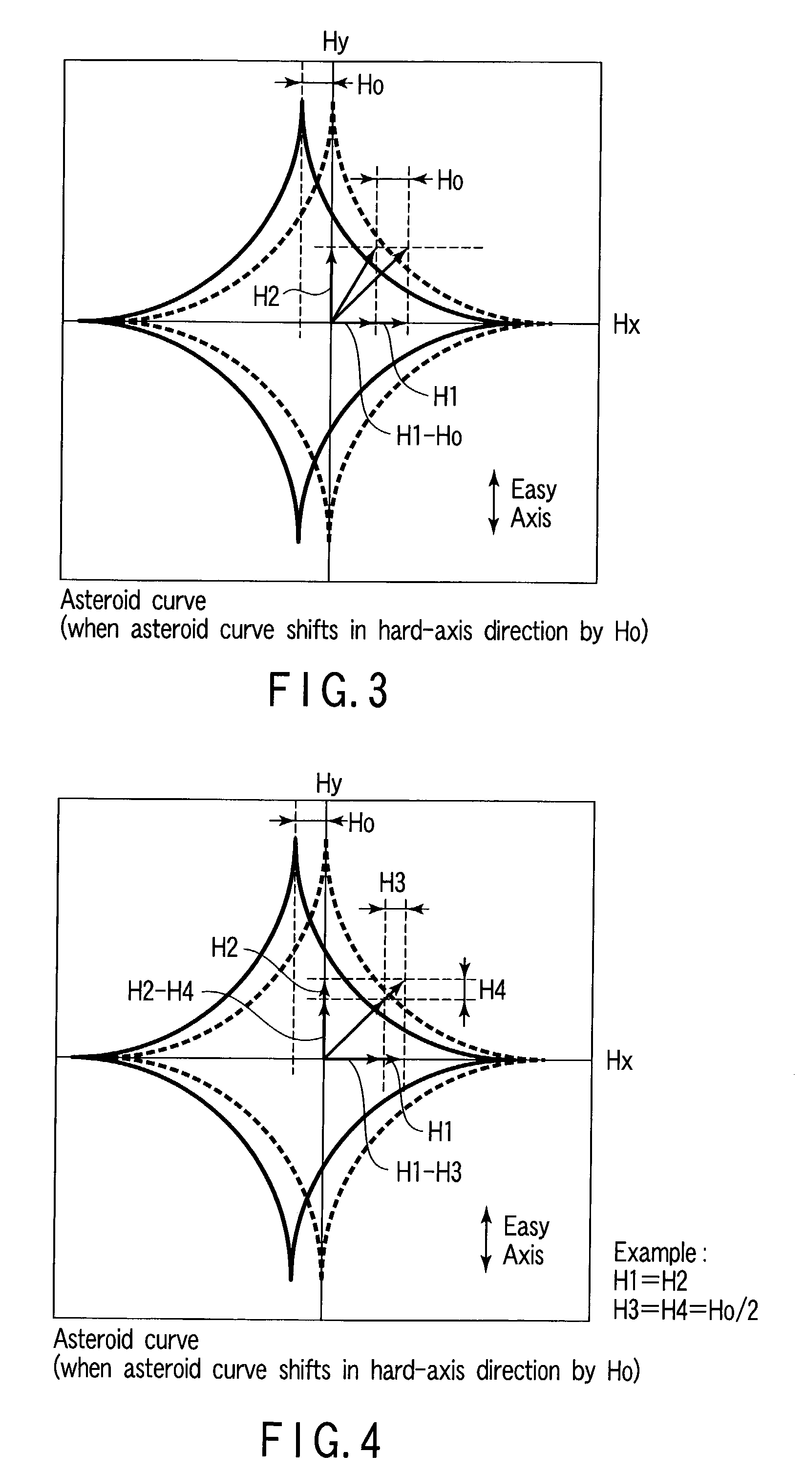
[0169]Example 3 is different from Example 1 in that the asteroid curve of a MTJ element shifts to the opposite side of the direction of the magnetic field (its direction changes in accordance with write data) in the easy-axis direction with respect to an ideal asteroid curve.
[0170]As shown in FIG. 7, a synthesized magnetic field necessary for magnetization inversion, which is determined on the basis of an ideal asteroid curve (broken line), is defined as {right arrow over (H1)}+{right arrow over (H2)}. H1 is a magnetic field in the X-axis (hard-axis) direction, and H2 is a magnetic field in the Y-axis (easy-axis) direction. In this case, a point that indicates the intensity of the synthesized magnetic field {right arrow over (H1)}+{right arrow over (H2)} is located outside the ideal asteroid curve.
[0171]In Example 3, assume that the asteroid curve (solid line) of a MTJ element of an actually manufactured magnetic random access memory shifts to the opposite side of the dir...
example 4
④ EXAMPLE 4
[0179]Like Examples 1 and 3, Example 4 will be proposed in correspondence with Example 2.
[0180]In Example 4, each of the intensities of the magnetic fields in the hard- and easy-axis directions is controlled in accordance with the offset amount independently of the direction (easy-axis direction) of the shift of an asteroid curve, thereby increasing the reliability of write operation.
[0181]As shown in FIG. 8, a synthesized magnetic field necessary for magnetization inversion, which is determined on the basis of an ideal asteroid curve (broken line), is defined as {right arrow over (H1)}+{right arrow over (H2)}. H1 is a magnetic field in the X-axis (hard-axis) direction, and H2 is a magnetic field in the Y-axis (easy-axis) direction. In this case, a point that indicates the intensity of the synthesized magnetic field {right arrow over (H1)}+{right arrow over (H2)} is located outside the ideal asteroid curve.
[0182]In Example 4, assume that the asteroid curve (solid line) of...
⑤ example 5
[0192]Principle 2 is based on an example in which the asteroid curve shifts in the easy-axis direction. The data value of a MTJ element is determined by the magnetizing direction in the easy-axis direction.
[0193]That is, in Principle 2, when the situation described in Example 1 (or Example 2) occurs in a specific MTJ element, the situation described in Example 3 (or Example 4) also occurs in the specific MTJ element. For example, assume that the situation described in Example 1 (or Example 2) occurs when data “1” is to be written in a specific MTJ element. At this time, the situation described in Example 3 (or Example 4) occurs when data “0” is to be written in the specific MTJ element.
[0194]Hence, Examples 1 and 3 (or Examples 2 and 4) may be combined.
[0195]More specifically, when, e.g., data “1” is to be written, the magnitude of the write current for the write word / bit line is controlled such that the synthesized magnetic field has an intensity given by {right arrow over (H1)}+({...
PUM
 Abstract
Description
Claims
Application Information
 - R&D
- Intellectual Property
- Life Sciences
- Materials
- Tech Scout
- Unparalleled Data Quality
- Higher Quality Content
- 60% Fewer Hallucinations
Browse by: Latest US Patents, China's latest patents, Technical Efficacy Thesaurus, Application Domain, Technology Topic, Popular Technical Reports.
© 2025 PatSnap. All rights reserved.Legal|Privacy policy|Modern Slavery Act Transparency Statement|Sitemap|About US| Contact US: help@patsnap.com


