Method of forming an improved AP1 layer for a TMR device

a technology of tmr device and ap1 layer, which is applied in the field of forming and structure of ap1 in, can solve the problems of introducing new problems, reducing the tmr ratio, and achieving the effect of improving the breakdown voltage and strong pinning

Active Publication Date: 2008-05-27
HEADWAY TECH INC
View PDF9 Cites 7 Cited by
  • Summary
  • Abstract
  • Description
  • Claims
  • Application Information

AI Technical Summary

Benefits of technology

[0017]It has been an object of at least one embodiment of the present invention to provide a TMR read head an having improved barrier breakdown without performance loss.
[0020]A further object of at least one embodiment of the present invention has been to enable performance tuning of the pinned layer and the barrier to be performed separately.
[0021]These objects have been achieved by forming the AP1 layer from two or more layers. Each layer (except the uppermost one that will interface with the tunneling layer) is exposed to a low energy plasma for a short time before the next layer is laid down. This results in a smooth surface, onto which to deposit the tunneling barrier layer, with no disruption of the surface crystal structure. This leads to TMR devices with improved breakdown voltages. Additionally, the structure of the AFM layer, as influenced by the AFM coupling layer, and the growth of the barrier layer, as modulated by the plasma treatment, can be independently adjusted, which means that both strong pinning and a smooth barrier can be simultaneously realized. A process for manufacturing the device is described. Said process requires minimal changes to current manufacturing processes for TMR devices.

Problems solved by technology

Conventional techniques, such as a plasma treatment of AP1, introduce new problems.
In particular, although such treatment does provide a topographically smoother surface for the barrier layer to grow on, it can also disrupt the atomic ordering at the interface between AP1 and the barrier layer, resulting in a decrease in the TMR ratio.

Method used


Image

  • Method of forming an improved AP1 layer for a TMR device
  • Method of forming an improved AP1 layer for a TMR device

Examples


Embodiment Construction

[0025]The basic requirements for TMR sensors are as follows:[0026]1) Low areal resistance (RA).[0027]2) High MR ratio[0028]3) Magnetically soft free layer having low magnetostriction[0029]4) Low interlayer coupling through barrier layer.[0030]5) Strong pinned layer.

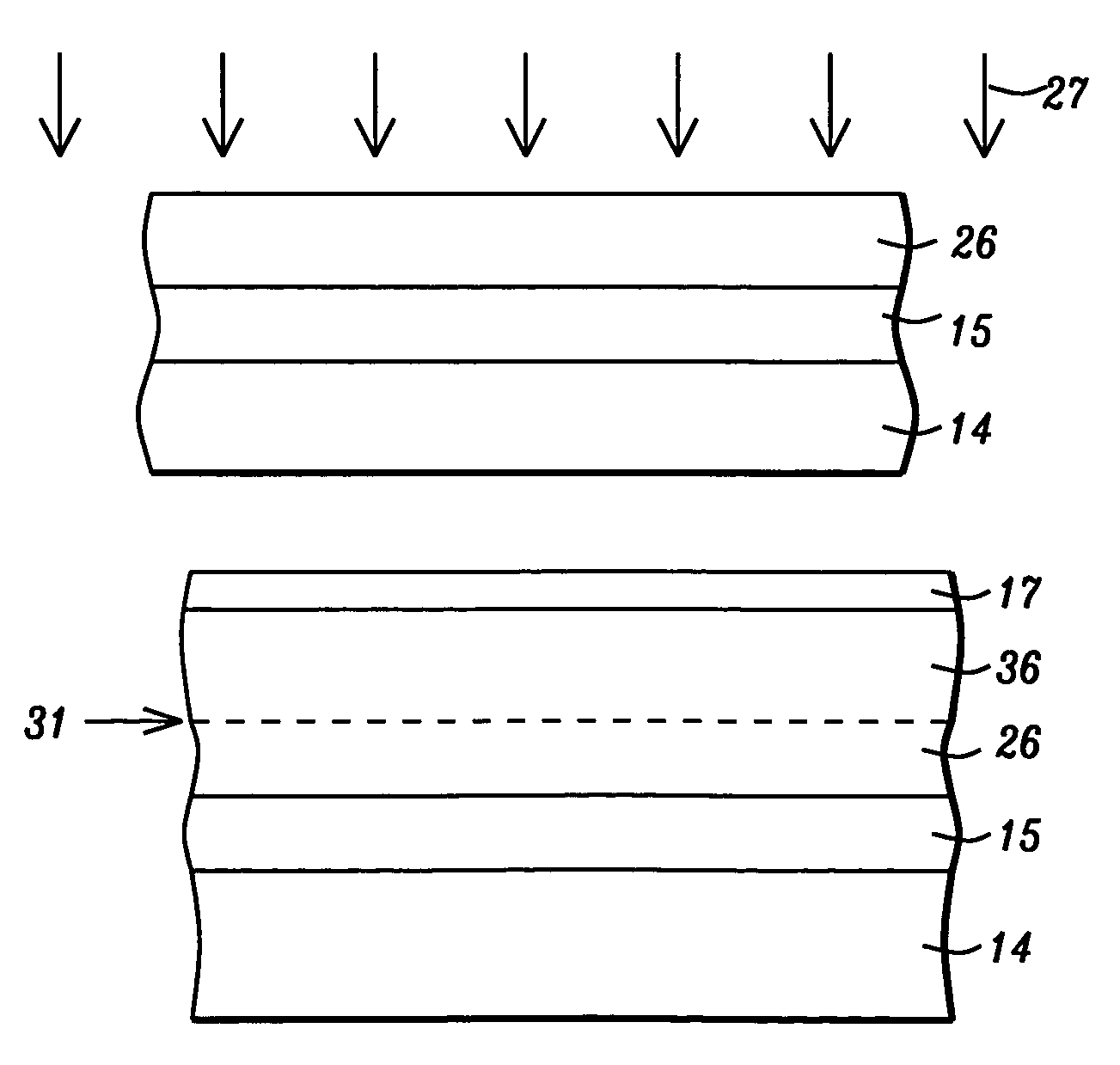
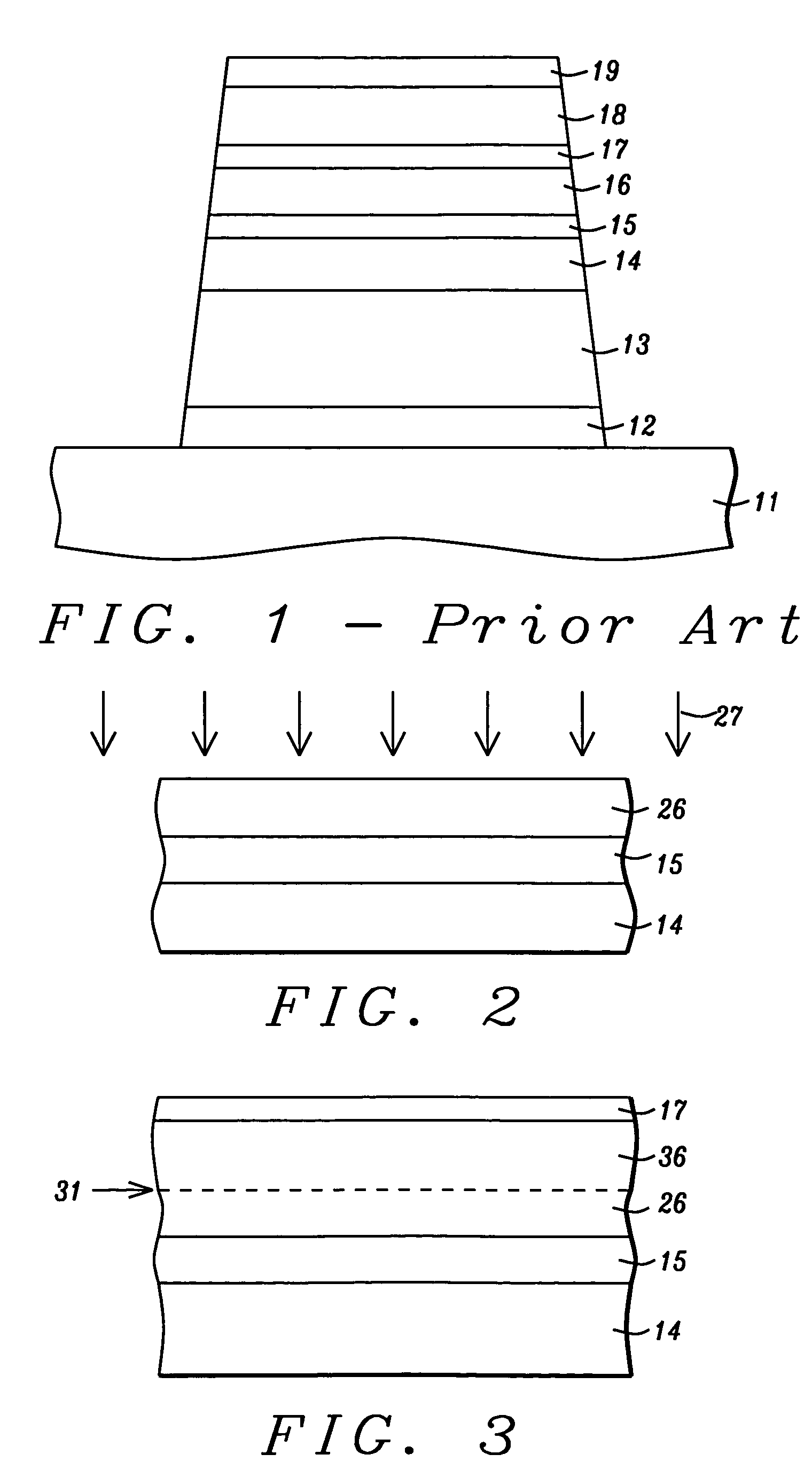
[0031]To meet the requirement of low RA (less than 10 ohm.μm2), the tunnel barrier has to be very thin; for example, less than 8 Å for an alumina barrier. Two major issues related to thin barriers are 1) higher pinhole density may cause stability problems for TMR sensors, and 2) large interlayer coupling may decrease the sensitivity of the TMR sensor. So it is essential to have a smooth underlying ferromagnetic layer on which to deposit the tunnel barrier layer.

[0032]The present invention teaches how to achieve smoother barrier growth without sacrificing other requirements of the TMR sensor such as maintaining the atomic ordering at the interface between AP1 and the barrier layer. We will illustrate the structure of the p...


PUM

PropertyMeasurementUnit
thicknessaaaaaaaaaa
thicknessaaaaaaaaaa
thicknessaaaaaaaaaa

Abstract

A TMR read head with improved voltage breakdown is formed by laying down the AP1 layer as two or more layers. Each AP1 sub-layer is exposed to a low energy plasma for a short time before the next layer is deposited. This results in a smooth surface, onto which to deposit the tunneling barrier layer, with no disruption of the surface crystal structure of the completed AP1 layer.

Description

FIELD OF THE INVENTION[0001]The invention relates to the general field of magnetic read heads with particular reference to the formation and structure of AP1 in magnetic tunnel junctions.BACKGROUND OF THE INVENTION[0002]The principle governing the operation of most magnetic read heads is the change of resistivity of certain materials in the presence of a magnetic field (magneto-resistance or MR). Magneto-resistance can be significantly increased by means of a structure known as a spin valve where the resistance increase (known as Giant Magneto-Resistance or GMR) derives from the fact that electrons in a magnetized solid are subject to significantly less scattering by the lattice when their own magnetization vectors (due to spin) are parallel (as opposed to anti-parallel) to the direction of magnetization of their environment.[0003]The key elements of a spin valve are a seed layer on which is an antiferromagnetic layer whose purpose is to act as a pinning agent for a magnetically pin...

Claims


Application Information

Patent Timeline
Patent Type & Authority Patents(United States)
IPC IPC(8): G11B5/193C23C14/48
CPCB82Y10/00B82Y40/00G11B5/3163G11B5/3903G11B5/3909H01F10/3272H01F41/303H01L43/12B82Y25/00Y10T29/49048Y10T29/49043Y10T29/49046Y10T29/49044Y10T29/49052Y10T29/49041H10N50/01
Inventor ZHAO, TONGTORNG, CHYU-JIUHWANG, HUI-CHUAN
Owner HEADWAY TECH INC
Why Eureka
Try Eureka