Check patentability & draft patents in minutes with Patsnap Eureka AI!

Sensor signal processing system and detector

a technology of sensor signal and processing system, applied in the direction of simultaneous indication of multiple variables, instruments, turn-sensitive devices, etc., can solve the problems of troublesome acquisition of correction data, difficult to perform consecutive corrections, and complicated system configuration, etc., and achieve the effect of simple configuration

Inactive Publication Date: 2008-05-27
FUJITSU LTD +1
View PDF15 Cites 2 Cited by
  • Summary
  • Abstract
  • Description
  • Claims
  • Application Information

AI Technical Summary

Benefits of technology

[0017]An object of the present invention is to provide a sensor signal processing system having a simple configuration for compensating temperature characteristics of an angular velocity sensor or the like responding to a change of the sensitivity-temperature characteristics thereof and to provide a detector that is used for the system.

Problems solved by technology

However, this method has some disadvantages in that it is difficult to perform consecutive corrections and that it is troublesome to obtain the correction data in advance and that a system configuration becomes complicated.
However, the conventional method proposed in the above-mentioned patent document 3 has a disadvantage in that temperature-gain characteristics of an amplifier circuit in a semiconductor integrated circuit are determined uniquely by temperature characteristics of an internal resistance.
However, designing and manufacturing a semiconductor integrated circuit takes a long time and needs high cost, so this method is not good in flexibility.
Therefore, it is necessary to use a multistage amplifier circuit, which causes a large scale of circuit and a higher cost of manufacturing the semiconductor integrated circuit.

Method used


Image

  • Sensor signal processing system and detector
  • Sensor signal processing system and detector
  • Sensor signal processing system and detector

Examples


first embodiment

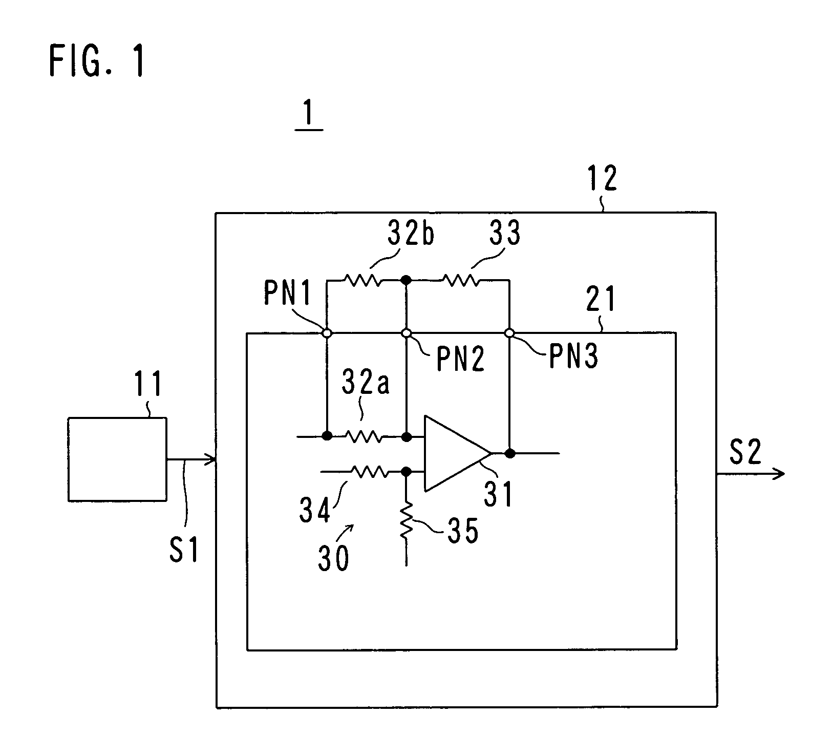
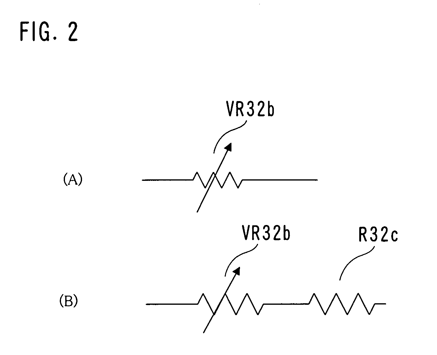
[0035]FIG. 1 is a diagram showing a configuration of a sensor signal processing system 1 according to a first embodiment of the present invention, and FIG. 2 is a diagram showing a configuration in which a variable resistor is used as an external input resistor.

[0036]As shown in FIG. 1, the sensor signal processing system 1 includes a sensor 11 and a detector 12. The sensor 11 converts a physical phenomenon into an electric signal, which is an output signal S1. The sensor 11 can be an angular velocity sensor, a speed sensor, a position sensor, a temperature sensor, a humidity sensor, a magnetic sensor, an optical sensor, a flow rate sensor or other various sensors, for example. In any case, the signal S1 of the sensor 11 varies in accordance with temperature. In other words, the sensor 11 has sensitivity-temperature characteristics, and a temperature coefficient thereof is β. The temperature coefficient β is a constant or is expressed by mathematical formulas or by a conversion tabl...

second embodiment

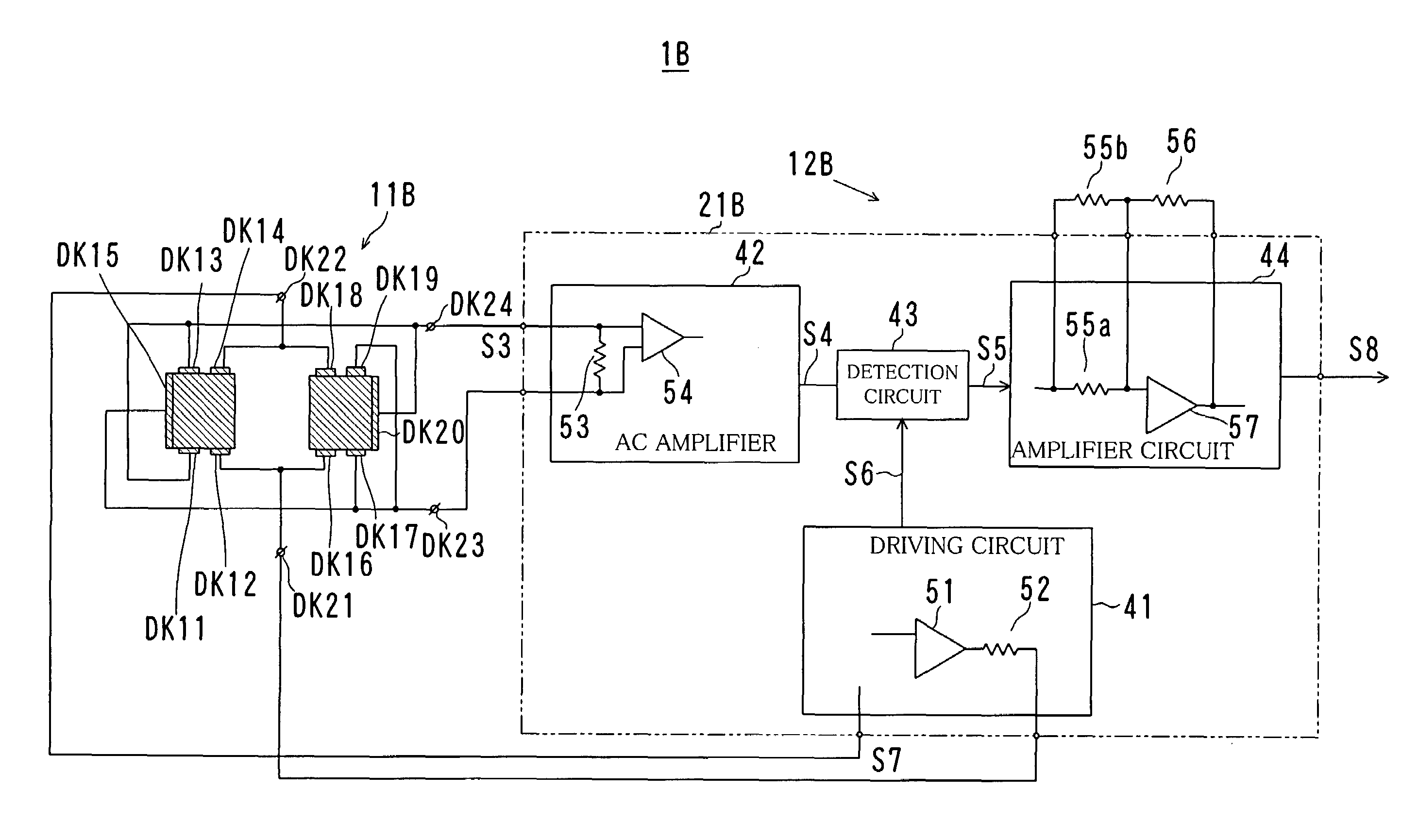
[0058]Next, a sensor signal processing system 1B according to a second embodiment of the present invention will be described. The sensor signal processing system 1B utilizes an angular velocity sensor (a gyro sensor) as the sensor, which outputs a detection signal corresponding to an angular velocity of an object. Therefore, the sensor signal processing system 1B can be called an angular velocity sensor system, an angular velocity detection device, a gyro sensor system, a gyro sensor or the like.

[0059]Note that description will be omitted or simplified about elements in the second embodiment having the same functions or actions as in the first embodiment.

[0060]FIG. 3 is a diagram showing a configuration of the sensor signal processing system 1B according to the second embodiment of the present invention, FIG. 4 is a circuit diagram showing a concrete example of a semiconductor integrated circuit 21B, FIG. 5 is a diagram showing an example of a relationship between a resistance RR55b...

example 1

[0087]Only the temperature characteristics of the amplifier circuit 44 are used for the compensation. More specifically, a resistor having a resistance RR32b of 1.1 MΩ and a temperature coefficient α2 of “0” is used as the external input resistor 32b. External resistors having no temperature coefficient are used for the limiting resistor 52 of the driving circuit 41 and the input resistor 53 of the AC amplifier 42.

[0088]In this case, the combined temperature coefficient α3 becomes 1100 ppm / ° C. from the above equation (4), and the temperature characteristics of the amplifier circuit 44, i.e., temperature characteristics of the entire semiconductor integrated circuit 21 become 1100 ppm / ° C., so the sensitivity-temperature characteristics −1100 ppm / ° C. of the angular velocity sensor 11B are canceled.

[0089]Together with the setting of the resistance RR32b to 1.1 MΩ, the feedback resistor 33 is adjusted so that the amplification factor A of the amplifier circuit 44 becomes a predetermi...


PUM


Abstract

A detector is made up of a semiconductor integrated circuit in a part, and the semiconductor integrated circuit includes a driving circuit, an AC amplifier, a detection circuit and an amplifier circuit. An input resistor that is connected to input terminals of an operational amplifier includes an internal input resistor made up of a semiconductor integrated circuit element and an external input resistor made up of an external discrete component connected to each other in parallel. Temperature characteristics of an angular velocity sensor is compensated by a temperature coefficient (α3) that is a combination of a temperature coefficient (α1) of the internal input resistor and a temperature coefficient (α2) of the external input resistor.

Description

BACKGROUND OF THE INVENTION[0001]1. Field of the Invention[0002]The present invention relates to a sensor signal processing system for processing an output signal of an angular velocity sensor (angular accelerometer) or the like for producing a detection signal that corresponds to a physical phenomenon and relates to a detector that is used for the system.[0003]2. Description of the Prior Art[0004]Conventionally, an angular velocity sensor (an angular accelerometer, also called a gyro sensor) for detecting an angular velocity of an object has been used for detection of shake or movement of a video camera, a navigation device, detection of a roll angle for determining a release timing of side air bags, or an attitude control of a vehicle or a robot.[0005]Such an angular velocity sensor includes a beam type and a tuning fork type. Among those types, a tuning fork gyro sensor is widely used because it can be vibrated easily and has a high Q value (see patent documents 1-3 below).[0006]...

Claims


Application Information

Patent Timeline
Patent Type & Authority Patents(United States)
IPC IPC(8): G01P3/00G01C19/00G01C19/56
CPCG01C19/56G01C19/00
Inventor NAKAZAWA, FUMIHIKOYACHI, MASANORIHANAZAWA, TOSHIO
Owner FUJITSU LTD
Features
  • R&D
  • Intellectual Property
  • Life Sciences
  • Materials
  • Tech Scout
  • Unparalleled Data Quality
  • Higher Quality Content
  • 60% Fewer Hallucinations
Learn More