Thread mill having flute twisting in direction opposite to rotating direction

a thread mill and flute technology, applied in the field of thread mills, can solve the problems of preventing the engagement of the internal thread with the external thread, affecting the performance of the internal thread, etc., and achieve the effect of reducing burrs

Active Publication Date: 2008-05-27
OSG
View PDF32 Cites 10 Cited by
  • Summary
  • Abstract
  • Description
  • Claims
  • Application Information

AI Technical Summary

Benefits of technology

[0023]In the thread mill constructed according to the invention, the at least one spiral flute defining the at least one cutting edge extends in the direction opposite to the rotating direction as seen in the direction away from the proximal end portion toward the distal end portion. Where the thread mill is designed to be rotated in a clockwise direction for forming the external or internal thread, the at least one spiral flute is arranged to twist in a counterclockwise direction. Where the thread mill is designed to be rotated in the counterclockwise direction for forming the thread, the at least one spiral flute is arranged to twist in the clockwise direction. This arrangement permits a portion of each cutting edge adjacent to a rear-side one of flanks (hereinafter simply referred to as “rear flank”) of each annular protrusion provides a positive rake rather than a negative rake, namely, provides a rake angle that is acute rather than obtuse. Therefore, the portion of each cutting edge adjacent to the rear flank of each annular protrusion has an improved cutting sharpness, advantageously restraining burrs from being left in an entrance opening of the hole or a chamfered portion of the formed thread, and leading to an improvement in accuracy of the formed thread.
[0024]In the thread mill according to the second aspect of the invention, the helix angle of each of the at least one spiral flute being not smaller than 5° enables the above-described portion of each cutting edge adjacent to the rear flank of each annular protrusion to provide the rake angle that is sufficiently acute, thereby assuring the improvement of the cutting sharpness. Meanwhile, the helix angle of each of the at least one spiral flute being not larger than 30° enables the cylindrical main body to have a sufficient degree of rigidity against a load forcing the main body to be inclined.
[0025]In the thread mill according to the sixth aspect of the invention, the profile of each annular protrusion is substantially identical with the profile of each ridge of the thread that is to be formed, and the difference of the major diameter and the minor diameter of each annular protrusion is substantially twice as large as the height or depth of the thread that is to be formed. In other words, the profile of each annular protrusion is configured to enable the cutting edge to cut the entirety of each thread ridge including its crest, thereby eliminating risk of presence of the burrs left in each crest in a complete thread portion of the formed thread. Therefore, since the burrs are restrained from being left in the entrance opening of the hole, i.e., in the chamfered portion of the formed thread, as described above, it is possible to minimize presence of the burrs in the entirety of the formed thread, and accordingly to further assure the improvement of the accuracy of the formed thread.
[0026]While the thread mill constructed according to the invention is suitable, particularly, for forming an internal thread in a blind hole, the thread mill can be used also for forming an internal thread in a through-hole. Further, the thread mill can be used not only for formation of an internal thread in an inner circumferential surface of the workpiece but also for formation of an external thread in an outer circumferential surface of the workpiece. Where the internal thread is formed in the blind hole, namely, where the formed thread has the chamfered portion only in the entrance opening of the hole, rather than both in the entrance and exit openings of the hole, it is possible to enable the formed thread to be provided with an excellent accuracy, as long as the presence of the burrs in the entrance opening of the hole is retrained.
[0029]In the thread forming method according to the eighth aspect of the invention in which the entrance opening edge of the hole is chamfered before the internal thread is formed in the inner circumferential surface of the hole, the thread mill constructed according to the invention can restrain burrs from being left in the chamfered portion of the internal thread. This feature eliminates necessity of implementing an additional chamfering step for removing the burrs from the formed internal thread. It is noted that the formation of the hole and the chamfering of the opening edge of the hole may be made by any cutting tool such as drill and countersink. Further, the formation of the hole and the chamfering of the opening edge of the hole does not have to be made by cutting operations but may be made by forging operations.
[0030]The number of the at least one annular protrusion formed on the outer circumferential surface of the cylindrical main body may be only one, so that the threading operation is performed by causing the thread mill to orbit about the axis of the circumferential surface of the workpiece a plural number of times. However, it is preferable that the at least one annular protrusion consists of a plurality of annular protrusions or at least three annular protrusions arranged in the axial direction, so that the thread having a predetermined length can be formed by causing the thread mill to orbit a less number of times such as only once.

Problems solved by technology

Therefore, the portion of each cutting edge adjacent to the rear flank of each annular protrusion cannot exhibit a satisfactory cutting performance, resulting in burrs left in an entrance opening of the hole or a chamfered portion of the formed internal thread, or burrs partially removed from the chamfered portion of the internal thread.
The burrs left in the chamfered portion of the internal thread is problematic, particularly, where the thread mill has annular protrusions each having a profile configured to cut each thread ridge including its crest, namely, where the burrs are unlikely to be left in each crest in a complete thread portion of the internal thread.
Such a burr remaining in the chamfered portion of the internal thread could impede engagement of the internal thread with an external thread.

Method used


Image

  • Thread mill having flute twisting in direction opposite to rotating direction
  • Thread mill having flute twisting in direction opposite to rotating direction
  • Thread mill having flute twisting in direction opposite to rotating direction

Examples


Embodiment Construction

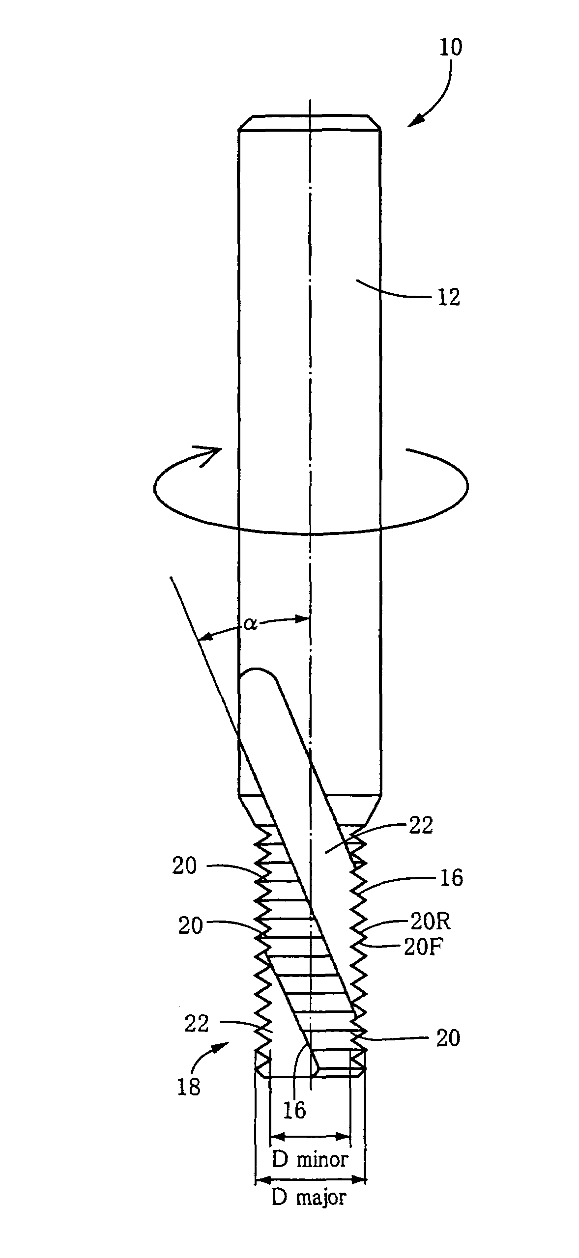
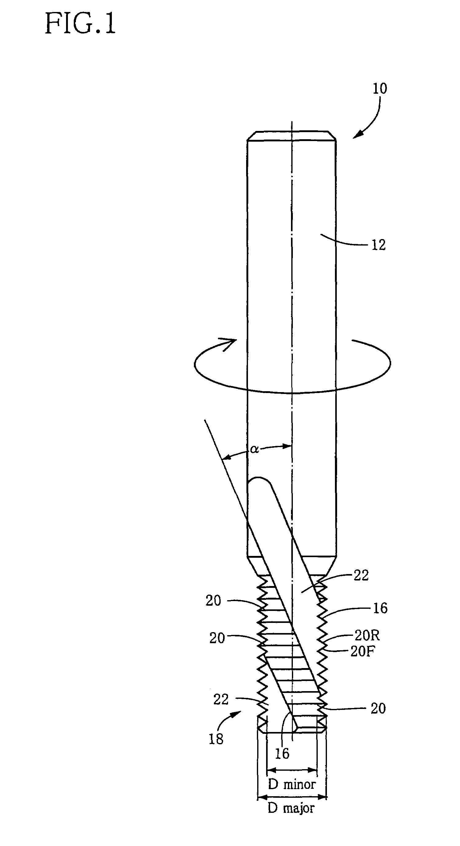
[0042]Referring first to FIG. 1, there will be described a thread mill 10 that is constructed according to an embodiment of the invention. The thread mill 10 includes: a cylindrical shank 12 that is to be attached through a suitable holder to a main spindle of a machine tool such as a machining center; and a cylindrical main body in the form of a fluted main body 18 that is coaxial and formed integrally with the shank 12. The fluted main body 18 has a multiplicity of annular protrusions 20 formed on its outer circumferential surface and arranged in axial direction of the main body 18 at a pitch between each adjacent pair of the annular protrusions 20 corresponding to a pitch of an internal thread 30 (see FIG. 2) that is to be machined by the thread mill 10. Each of the annular protrusions 20 has a profile of each ridge of the internal thread 30. Unlike a helical protrusion provided in a tap, each annular protrusion 20 of the thread mill 10 extends in a circumferential direction of t...


PUM

PropertyMeasurementUnit
helix angleaaaaaaaaaa
diameteraaaaaaaaaa

Abstract

A thread mill that is to be moved along a helical interpolation path while being rotated about an axis of the thread mill in a rotating direction, for forming a thread in a circumferential surface of a workpiece. The thread mill includes a cylindrical main body having (a) at least one spiral flute formed in an outer circumferential surface of the cylindrical main body, and (b) at least one cutting edge each provided by a rear-side one of widthwise opposite edges, as viewed in the rotating direction, of a corresponding one of the at least one spiral flute. Each of the at least one spiral flute extends in a direction opposite to the rotating direction as viewed in a direction away from a proximal end of the cylindrical main body toward a distal end of the cylindrical main body. Also disclosed is a method of forming the thread by using the thread mill.

Description

BACKGROUND OF THE INVENTION[0001]1. Field of the Invention[0002]This invention relates in general to a thread mill for forming an external or internal thread in an outer or inner circumferential surface of a workpiece, and more particularly to such a thread mill that is capable of forming the thread without undesirable debris or burrs being left on the threaded circumferential surface.[0003]2. Discussion of the Related Art[0004]As a kind of tool for forming an internal thread in an inner circumferential surface of a hole previously formed in a workpiece, there is known a thread mill including a cylindrical main body having annular protrusions formed on its outer circumferential surface. Each of the annular protrusions has a profile of each ridge of the internal thread that is to be formed, and extends in a circumferential direction of the cylindrical main body without extending in an axial direction of the cylindrical main body for providing no lead. The cylindrical main body has fl...

Claims


Application Information

Patent Timeline
Patent Type & Authority Patents(United States)
IPC IPC(8): B23G5/00B23G5/06B23G5/18
CPCB23G1/32B23G5/18B23G2200/48Y10T409/30056Y10T407/1948Y10T407/172Y10T409/300112
Inventor ANDOH, HARUYASUNAKAJIMA, TAKAYUKI
Owner OSG
Why Eureka
Try Eureka